Head-mountable apparatus

Inactive Publication Date: 2010-12-30
CANON KK
View PDF25 Cites 37 Cited by
  • Summary
  • Abstract
  • Description
  • Claims
  • Application Information

AI Technical Summary

Benefits of technology

[0009]The present invention provides, in consideration of the aforementioned problems, a head-mountable apparatus which allows an easy adjustment operation since the apparatu

Problems solved by technology

However, only an increase in holding force makes the observer feel discomfort.
However, the strong pressing force on the temporal regions may lead to a feeling of discomfort.
The mounting mechanism disclosed in Japanese Patent Laid-Open No. 08-086974 does not allow any adjustment since it has no temporal adjustment members and depends on an elastic force of an elastic member.
Henc

Method used


Image

  • Head-mountable apparatus
  • Head-mountable apparatus
  • Head-mountable apparatus

Examples


first embodiment

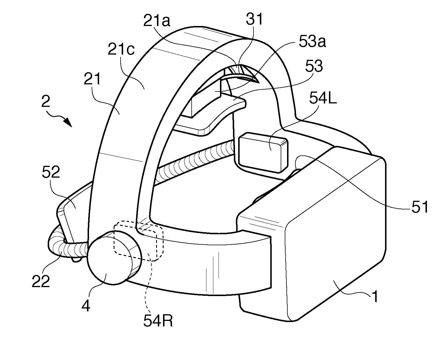
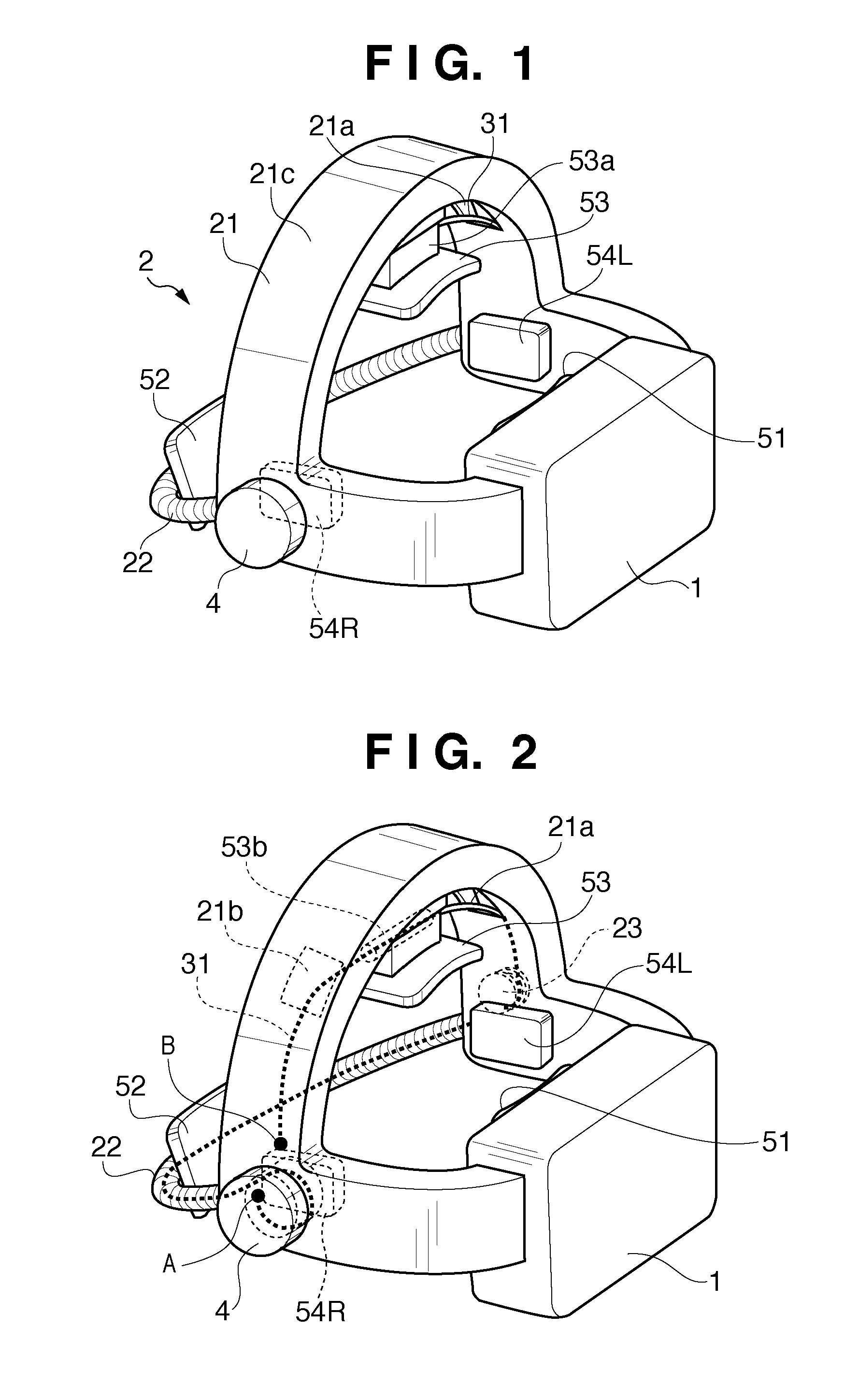
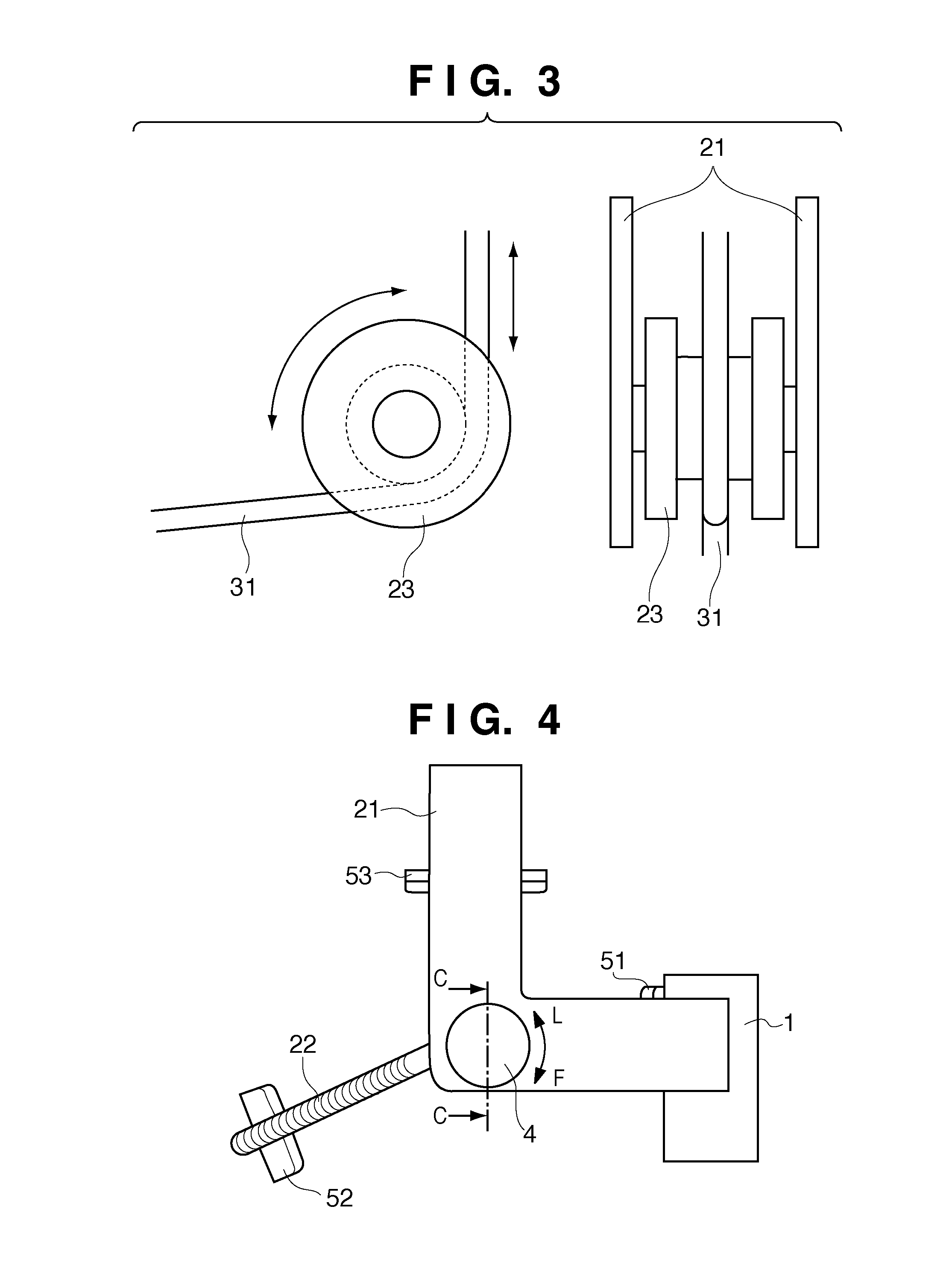
[0025]The arrangement of a head-mountable display (to be abbreviated as “HMD” hereinafter) according to the first embodiment of the present invention will be described below with reference to FIG. 1. An HMD includes a display unit 1 required to present a video picture to an observer, and a head-mounting unit 2 required to hold the display unit 1 in front of the eyes of the observer. In the display unit 1, a display element which displays a video picture, and an optical system which enlarges the video picture of that display element and guides it to the eyes of the observer are arranged (neither are shown). The display unit 1 is attached to a rigid frame 21. The rigid frame has a shape that extends to right and left temporal regions along a surrounding portion of the head and steps over a parietal region. On the parietal region of the rigid frame 21, holes 21a and 21b required to position (lace) an elongate member such as a wire 31 are formed (see FIG. 2). An extendable elongate memb...

second embodiment

[0044]An HMD according to the second embodiment will be described below with reference to FIG. 8. The same reference numerals in FIG. 8 denote the same components as those described in the first embodiment, and a detailed description thereof will not be repeated.

[0045]Right and left adjustment unit 8R and 8L, which serve as adjustment unit at the time of mounting, are pivotally attached to a rigid frame 21. One end of an occipital wire 32 whose length changes by an operation is attached to the right adjustment unit 8R, and one end of a parietal wire 33 is attached to the left adjustment unit 8L. The occipital wire 32 passes through an elastic tube 22 from the right adjustment unit 8R, and the other end thereof is attached to a left rear portion (at a connecting point M) of the rigid frame 21. On the other hand, one end of the parietal wire 33, whose length changes by an operation, is attached to the left adjustment unit 8L, and the parietal wire 33 passes through a parietal region o...

third embodiment

[0052]An HMD according to the third embodiment will be described below with reference to FIG. 10. The same reference numerals in FIG. 10 denote the same components as those described in the first and second embodiments, and a detailed description thereof will not be repeated. An adjustment unit 9 serving as an adjustment unit is arranged on a parietal region of a rigid frame 21. One end of a wire 34 is attached to the adjustment unit 9 (at connecting point P). The wire 34 passes through a right parietal region of the rigid frame 21 from the adjustment unit 9, then passes through an elastic tube 22 via a holding member 23, and the other end thereof is fixed to a left temporal region in the rigid frame 21 (at connecting point unit S). FIG. 11 is a sectional view of the adjustment unit 9. The adjustment unit 9 incorporates a shaft 21e, which fits with a one-way clutch 44, in the rigid frame 21, and the same mechanism as the right adjustment unit 8R used in the second embodiment. Then, ...


PUM


Abstract

A head-mountable apparatus mountable on a head of an observer comprises a first pressing member which presses a first portion of the head; a second pressing member which presses a second portion of the head; and adjustment unit adapted to move the first pressing member and the second pressing member to positions where the first pressing member and the second pressing member respectively press the first portion and the second portion.

Description

BACKGROUND OF THE INVENTION[0001]1. Field of the Invention[0002]The present invention relates to a head-mountable apparatus.[0003]2. Description of the Related Art[0004]As a device that is mounted on a head during use, a head-mountable display is well-known. A head-mountable display is commonly used since it allows an observer to readily view a video picture on a large screen, allows for easy stereoscopic vision, and is movable together with the observer. As a mounting mechanism of the head-mountable display, a mechanism which tightens around a surrounding portion of the head by a belt-like member, and a mechanism which includes frontal and occipital pressing members, and allows attachment / detachment of the head-mountable display by pressing or releasing the occipital pressing member against or from the head by moving that member in the back-and-forth directions are well-known.[0005]When an observer moves the head from side to side and up to down, a display unit of the head-mountabl...

Claims


Application Information

Patent Timeline
IPC IPC(8): B65H75/40A45F5/00
CPCG02B27/0176A42B1/247
Inventor NAKABAYASHI, TAKAAKIYASUDA, TOSHIYUKIISHINO, TOSHIKISAITO, YOSHIHIROOKUMA, TOSHIYUKIMIYATA, KAZUHIDE
Owner CANON KK
Why Eureka
Try Eureka