Jacking column for concrete drilling and cutting

Inactive Publication Date: 2010-12-30
TRACTIVE
View PDF19 Cites 6 Cited by
  • Summary
  • Abstract
  • Description
  • Claims
  • Application Information

AI Technical Summary

Benefits of technology

[0007]For example, in cutting or drilling operations where the jacking column is secured between the floor and ceiling of a structure, the operator uses the speed drive to quickly extend the column to a length closely corresponding to the distance between the floor and ceiling. Once the column sections reach this intermediate position, the screw drive is engaged and operated

Problems solved by technology

Low cost precision cutting and drilling requirements have only further increased the need for columns that can be quickly and securely installed without sacrificing safety.
Conventional tool-supporting columns suffer from various problems and fail

Method used


Image

  • Jacking column for concrete drilling and cutting
  • Jacking column for concrete drilling and cutting
  • Jacking column for concrete drilling and cutting

Examples


Embodiment Construction

[0022]The present invention is susceptible of embodiment in many different forms. While the drawings illustrate, and the specification describes, certain preferred embodiments of the invention, it is to be understood that such disclosure is by way of example only. There is no intent to limit the principles of the present invention to the particular disclosed embodiments.

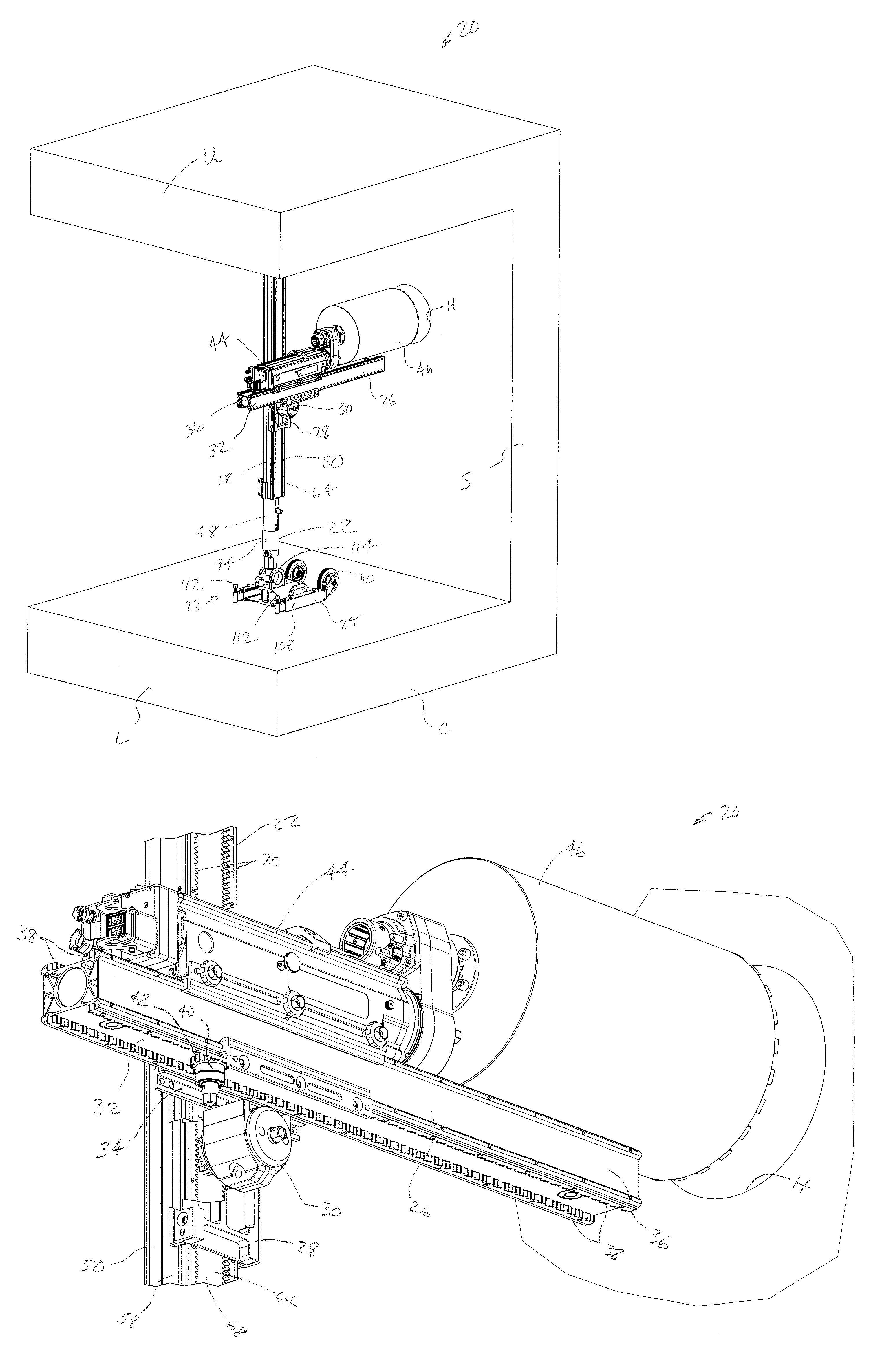
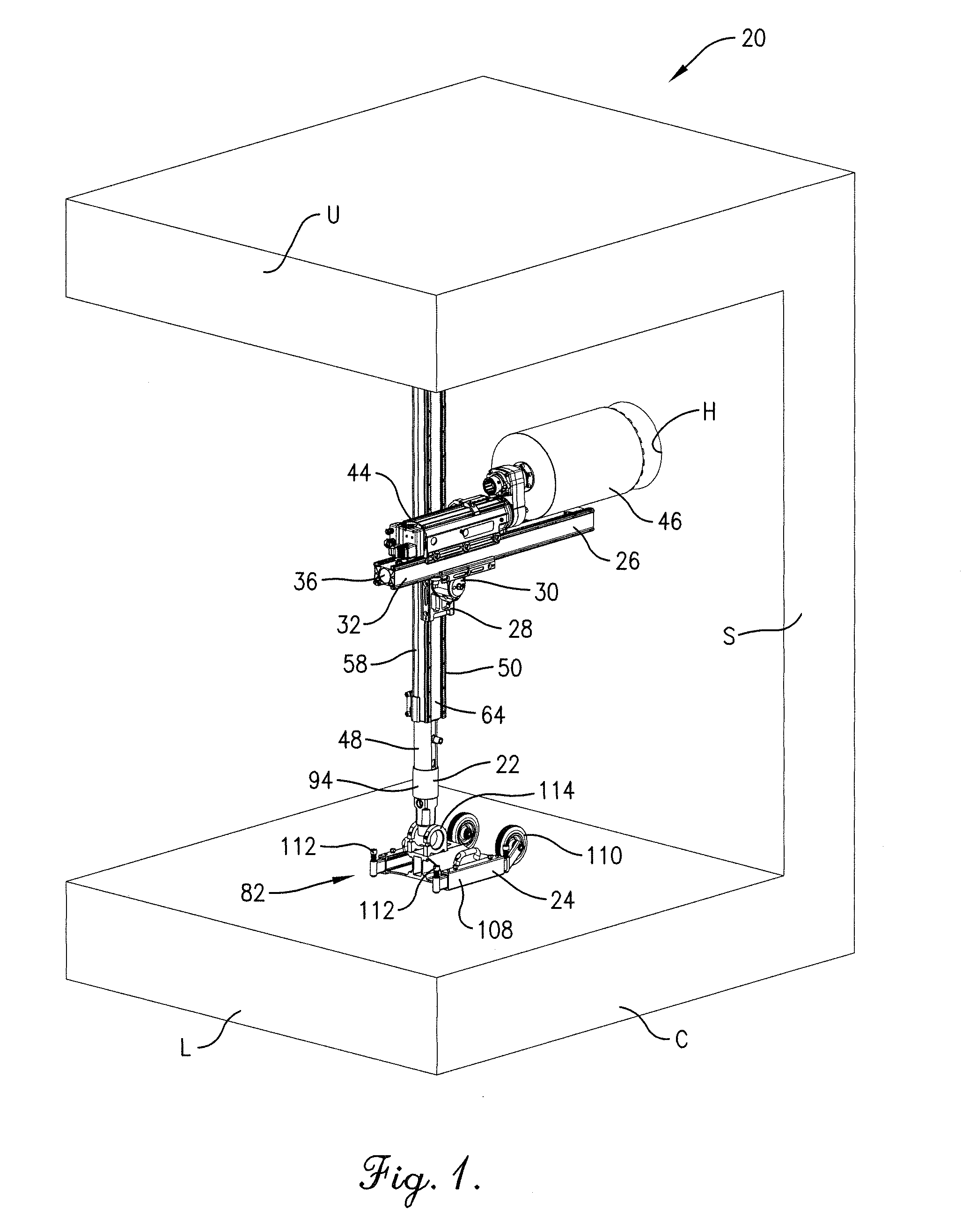
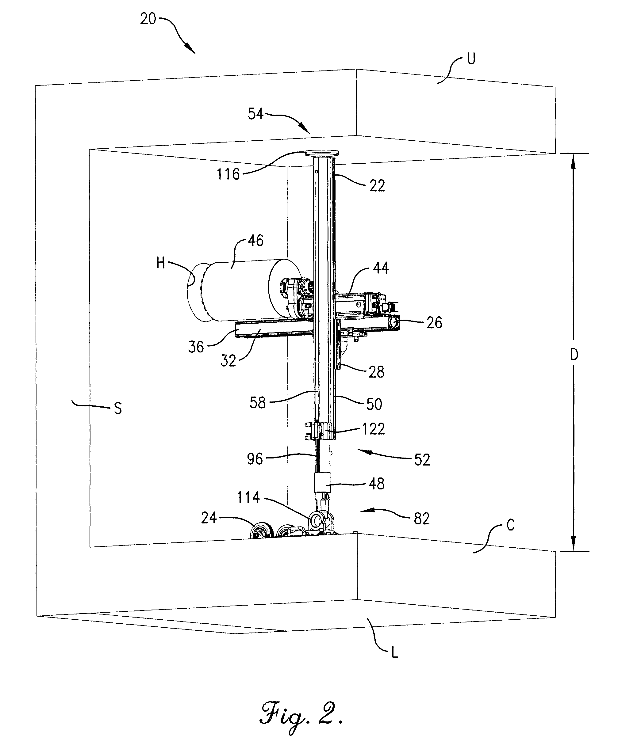
[0023]Initially referring to FIGS. 1-3, a drilling and cutting assembly 20 is illustrated for use in drilling a hole H in a concrete structure C. However, the assembly 20 is configured for various drilling and cutting operations in structure C, particularly where large static compression loads (often in excess of several tons) and dynamic loads are generated in securing the assembly 20 and conducting the drilling or cutting operation. The structure C includes parallel upper and lower walls U,L and sidewall S. As will be discussed further, the assembly 20 is secured in an upright orientation between upper and lower wa...


PUM


Abstract

An adjustable length jacking column for supporting a cutting or drilling tool between spaced apart surfaces is disclosed. A speed drive serves to quickly adjust the column sections to an intermediate position closely corresponding to the distance between the spaced apart surfaces. A selectively engageable screw drive is configured to shift the column sections from the intermediate position to a secured position, in which the column length corresponds to fixed securement between the surfaces. The screw drive is drivingly connected between the column sections to shift the column sections relative to one another when engaged, and is drivingly disconnected from at least one of the column sections when disengaged so as to avoid interfering with relative shifting of the column sections by the speed drive.

Description

BACKGROUND OF THE INVENTION[0001]1. Field of the Invention[0002]The present invention relates generally to an extendable column for supporting drilling and cutting equipment between spaced apart surfaces. More particularly, the present invention concerns a column utilizing a screw drive for reliably securing the column in place.[0003]2. Discussion of the Prior Art[0004]In cutting and drilling operations, one or more columns are commonly secured between spaced surfaces (e.g., the floor and ceiling of a structure) to support the cutting or drilling tool (e.g., a circular sawing machine, a chain or wire saw, a boring tool, etc.) during operation thereof. It is important that the column firmly support the tool so that unintended tool movement is avoided. This becomes of greater significance in concrete cutting and drilling operations, as the column has to counteract the significant operational loads experienced by the tool. Low cost precision cutting and drilling requirements have only ...

Claims


Application Information

Patent Timeline
IPC IPC(8): B66F3/16
CPCB25H1/0064B25H1/0042
Inventor JOHNSEN, ANDERS E. T.
Owner TRACTIVE
Why Eureka
Try Eureka