Braking system architecture for an aircraft fitted with electromechanical brakes

a technology of electromechanical brakes and braking system, which is applied in the direction of aircraft braking arrangements, instruments, navigation instruments, etc., can solve the problem of requiring long cables to be used, and achieve the effect of saving weigh

Active Publication Date: 2010-12-30
SAFRAN LANDING SYSTEMS
View PDF8 Cites 5 Cited by
  • Summary
  • Abstract
  • Description
  • Claims
  • Application Information

AI Technical Summary

Benefits of technology

[0009]Thus, the provisions of the invention enable substantial weight savin

Problems solved by technology

Nevertheless, this positioning requires long cables to be used, in particular cables that are grouped toge

Method used


Image

  • Braking system architecture for an aircraft fitted with electromechanical brakes
  • Braking system architecture for an aircraft fitted with electromechanical brakes

Examples


Embodiment Construction

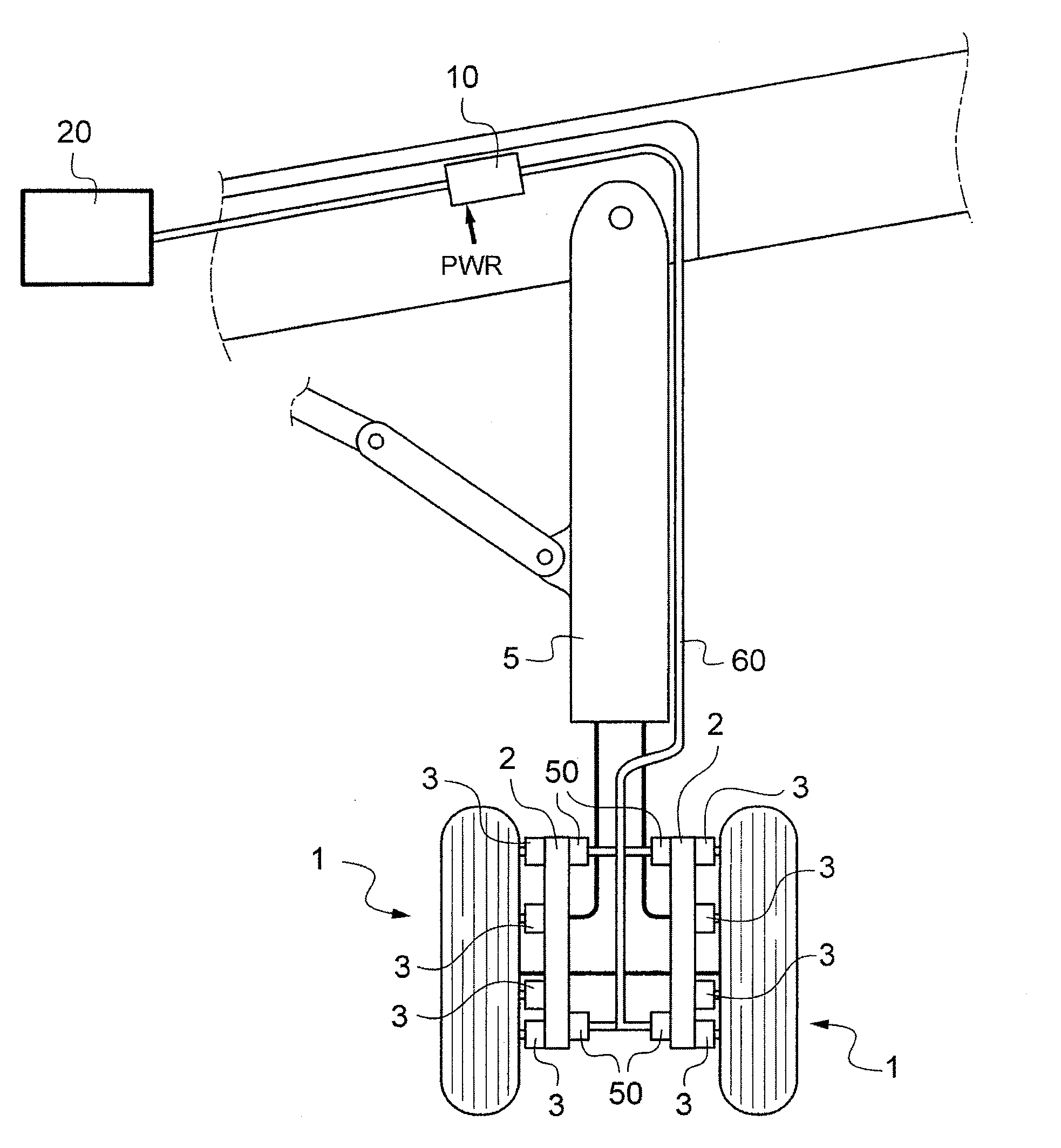
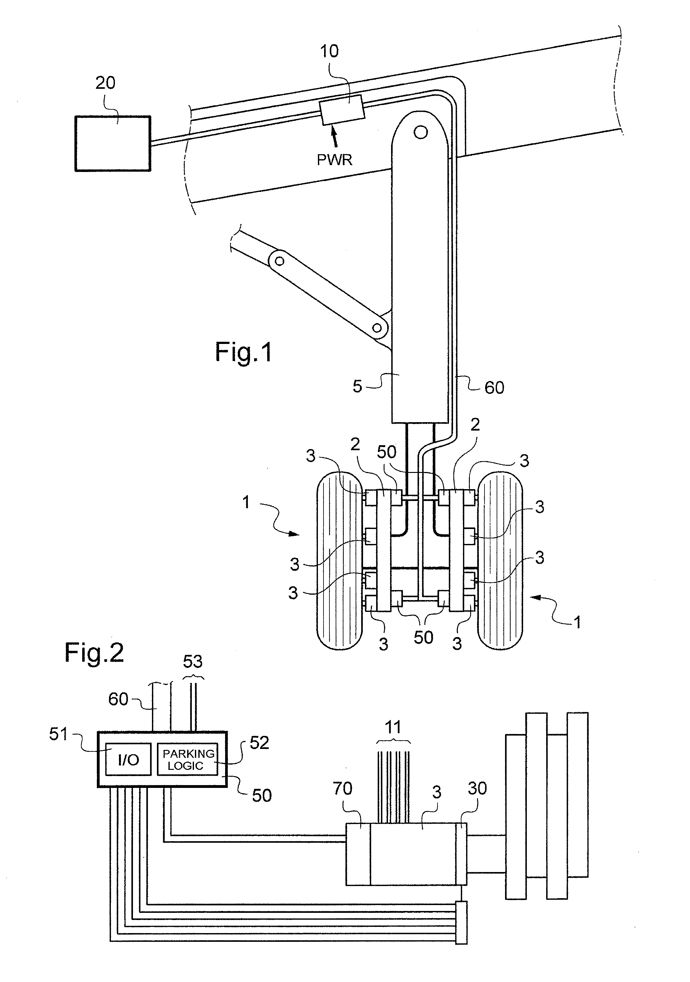
[0013]FIG. 1 shows a braking system in a first embodiment of the invention, comprising a certain number of brake wheels 1 fitted with brakes 2 having electromechanical actuators 3. The wheels are carried at the bottom of an undercarriage 5.

[0014]The electromechanical actuators in this example are fitted with electric motors for selectively moving a pusher in order to apply a braking force on disks. The motors are powered by one or more controllers 10 (known as electromechanical actuator controllers or EMACs), essentially comprising an inverter serving to deliver electrical power in compliance with braking setpoints generated by a braking computer 20. For this purpose, the controllers 10 are connected to high power networks and they deliver this power to the actuators 3 by means of high power cables going down along the undercarriages. Each controller 10 is connected to an actuator 3 by means of three power cables delivering respective phases to the motor, and given overall reference...


PUM


Abstract

The invention relates to a braking system architecture for an aircraft fitted with electromechanical brakes including at least one electromechanical actuator. In accordance with the invention, the architecture comprises at least one proximity unit disposed in the proximity of the brakes at the bottom of the undercarriage and including input/output means for collecting and calibrating at least signals coming from sensors associated with the brakes, and for transmitting the signals as processed in this way to control members for controlling the actuators by means of a communications bus running along the undercarriage, the proximity unit further including control means for controlling the blocking members of the actuators.

Description

[0001]The invention relates to a braking system architecture for an aircraft fitted with electromechanical brakes.TECHNOLOGICAL BACKGROUND OF THE INVENTION[0002]In known architectures, braking electromechanical actuators are installed at the wheels of the aircraft, and they receive their power from controllers that are generally situated in a bay close to the undercarriages carrying the wheels. The controllers receive orders from one or more braking computers installed in an avionics bay, generally located towards the nose of the aircraft, close to the cockpit.[0003]Positioning the braking controllers and computers in bays enables these elements to be placed in an environment that is favorable and less exposed, thereby contributing to increasing their reliability. Nevertheless, this positioning requires long cables to be used, in particular cables that are grouped together in a harness extending between the actuators and the controllers and running along the undercarriages. Such cab...

Claims


Application Information

Patent Timeline
IPC IPC(8): B64C25/44B64C25/42
CPCB60T13/741B60T8/1703
Inventor COLIN, EMMANUELTHIBAULT, JULIENGIROD, PIERRE
Owner SAFRAN LANDING SYSTEMS
Why Eureka
Try Eureka