Variable valve timing control apparatus and method for controlling variable valve timing device

a timing control and variable valve technology, applied in electrical control, non-mechanical valves, instruments, etc., can solve the problems of inability to maintain the stability of idling operation after engine start, abnormal condition needs to be immediately detected, and engine startability may be impaired

Active Publication Date: 2010-12-30
DENSO CORP
View PDF5 Cites 11 Cited by
  • Summary
  • Abstract
  • Description
  • Claims
  • Application Information

AI Technical Summary

Benefits of technology

[0007]According to one aspect of the present invention, a variable valve timing control apparatus for a variable valve timing device for an internal combustion engine, the variable valve timing device driven by a hydraulic pressure and configured to change a VCT phase of a camshaft relative to a crankshaft to control a valve timing, the variable valve timing device including i) a lock pin configured to lock the VCT phase in an intermediate lock phase between a most retarded phase and a most advanced phase of a controllable range and ii) a hydraulic pressure control device configured to control a hydraulic pressure to drive the variable valve timing device and the lock pin, the variable valve timing control apparatus configured to control the hydraulic pressure control device to project the lock pin to lock the VCT phase in the intermediate lock phase when a lock request occurs, the variable valve timing control apparatus comprises a VCT phase calculating unit configured to calculate the VCT phase based on a phase difference between a time point, in which a crank angle sensor generates a crank angle signal at a predetermined crank angle with an operation of the internal combustion engine, and a time point, in which a cam angle sensor generates a cam angle signal at a predetermined cam angle with the operation of the internal combustion engine. The variable valve timing control apparatus further comprises a reference phase learning unit configured to learn one of the most retarded phase, the most advanced phase, and the intermediate lock phase, as a reference phase. The variable valve timing control apparatus further comprises a VCT phase control unit configured to set a target phase according to a learning value of the reference phase and configured to control the hydraulic pressure control device such that the VCT phase coincides with the target phase. The variable valve timing control apparatus further comprises a lock abnormality monitor unit configured to monitor a change in the VCT phase and determine that the VCT phase has passed through the intermediate lock phase when: i) the lock request occurs in a period before the reference phase learning unit completes learning of the reference phase; and ii) the monitored change in the VCT phase becomes greater than a threshold. The threshold is set to be greater than a sum of i) a design value of a phase difference between the intermediate lock phase and one of the most retarded phase and the most advanced phase and ii) a range of a product variation of the phase difference.
[0008]According to another aspect of the present invention, a variable valve timing control apparatus for a variable valve timing device for an internal combustion engine, the variable valve timing device driven by a hydraulic pressure and configured to change a VCT phase of a camshaft relative to a crankshaft to control a valve timing, the variable valve timing device including i) a lock pin configured to lock the VCT phase in an intermediate lock phase between a most retarded phase and a most advanced phase of a controllable range and ii) a hydraulic pressure control device configured to control a hydraulic pressure to drive the variable valve timing device and the lock pin, the variable valve timing control apparatus configured to control the hydraulic pressure control device to project the lock pin to lock the VCT phase in the intermediate lock phase when a lock request occurs, the variable valve timing control apparatus comprises a VCT phase calculating unit configured to calculate the VCT phase based on a phase difference between a time point, in which a crank angle sensor generates a crank angle signal at a predetermined crank angle with an operation of the internal combustion engine, and a time point, in which a cam angle sensor generates a cam angle signal at a predetermined cam angle with the operation of the internal combustion engine. The variable valve timing control apparatus further comprises a reference phase learning unit configured to learn one of the most retarded phase, the most advanced phase, and the intermediate lock phase, as a reference phase. The variable valve timing control apparatus further comprises a VCT phase control unit configured to set a target phase according to a learning value of the reference phase and configured to control the hydraulic pressure control device such that the VCT phase coincides with the target phase. When the lock request occurs in a period in which learnin

Problems solved by technology

Therefore, when an abnormal condition occurs, and a lock pin is not properly projected to perform a locking action in response to a lock request, startability of the engine may be impaired, and stability of an idling operation after an engine start cannot be maintained.
Therefore, when such an abnormal condition occurs, and when the lock pin cannot be properly projected, such a

Method used


Image

  • Variable valve timing control apparatus and method for controlling variable valve timing device
  • Variable valve timing control apparatus and method for controlling variable valve timing device
  • Variable valve timing control apparatus and method for controlling variable valve timing device

Examples


first embodiment

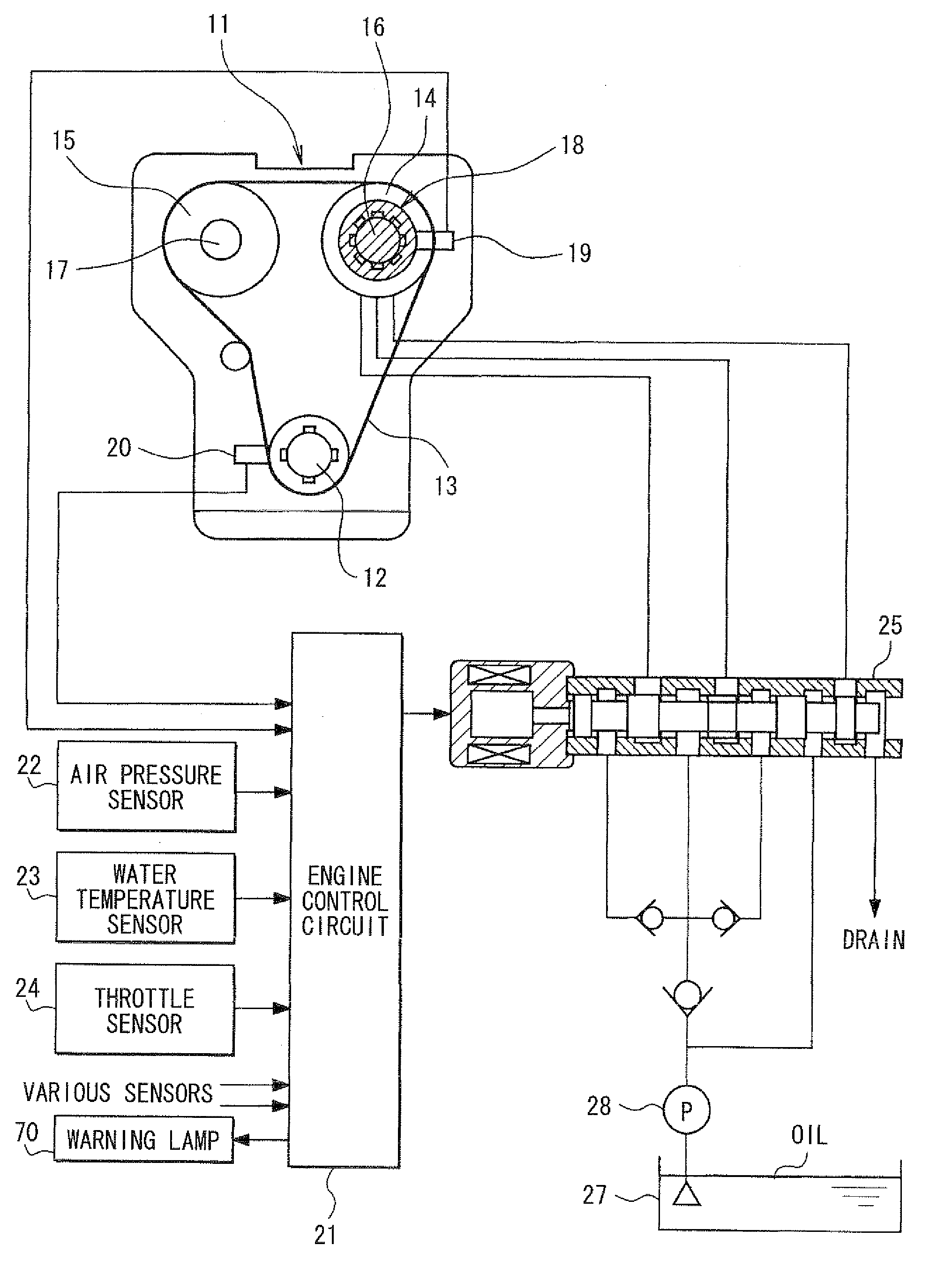
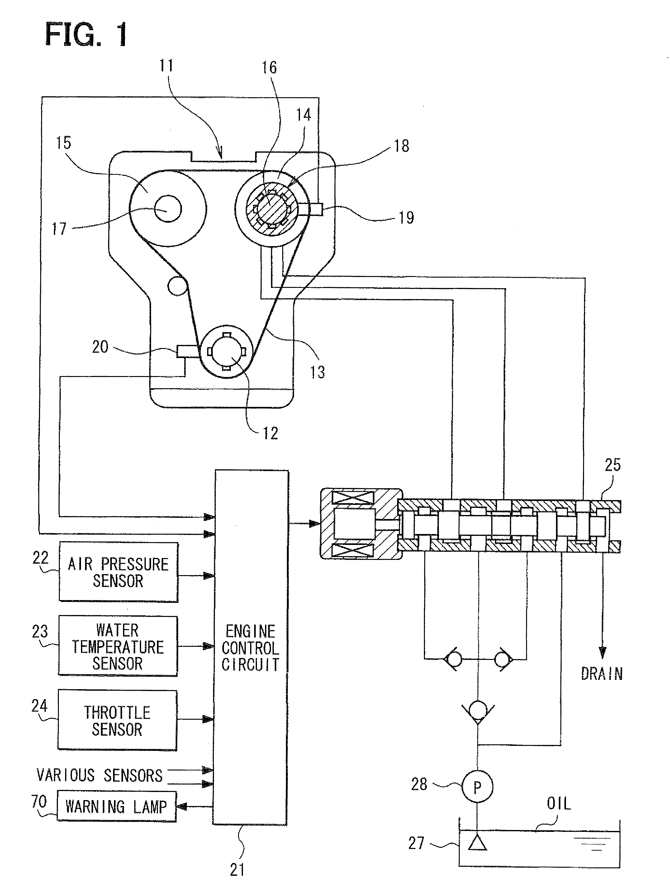
[0023]As follows, a first embodiment will be described with reference to FIGS. 1 to 7. As shown in FIG. 1, in an internal combustion engine 11, an output power of a crankshaft 12 is transmitted to an intake-side camshaft 16 and an exhaust-side camshaft 17 via sprockets 14, 15 and a timing chain 13. The intake-side camshaft 16 is provided with a variable valve timing device 18 (variable cam timing: VCT) for controlling an advance (VCT phase) of the intake-side camshaft 16 relative to the crankshaft 12.

[0024]A cam angle sensor 19 is provided on the outer circumferential periphery side of the intake-side camshaft 16 to output a pulse of a cam angle signal at a predetermined cam angle interval. A crank angle sensor 20 is provided on the outer circumferential periphery side of the crankshaft 12 to output a pulse of a crank angle signal at a predetermined crank angle interval. The output signals of the cam angle sensor 19 and the crank angle sensor 20 are inputted to an engine control cir...

second embodiment

[0071]Subsequently, a second embodiment will be described with reference to FIG. 8. An intermediate-lock-phase-pass-through determination processing of FIG. 8 according to the present second embodiment is produced by adding a processing of step 119 subsequently to step 118 of the intermediate-lock-phase-pass-through determination processing of FIG. 7 described in the first embodiment. Other processings than additional step 19 is substantially equivalent to that of the first embodiment. The structure other than additional step 19 is substantially equivalent to that of the first embodiment.

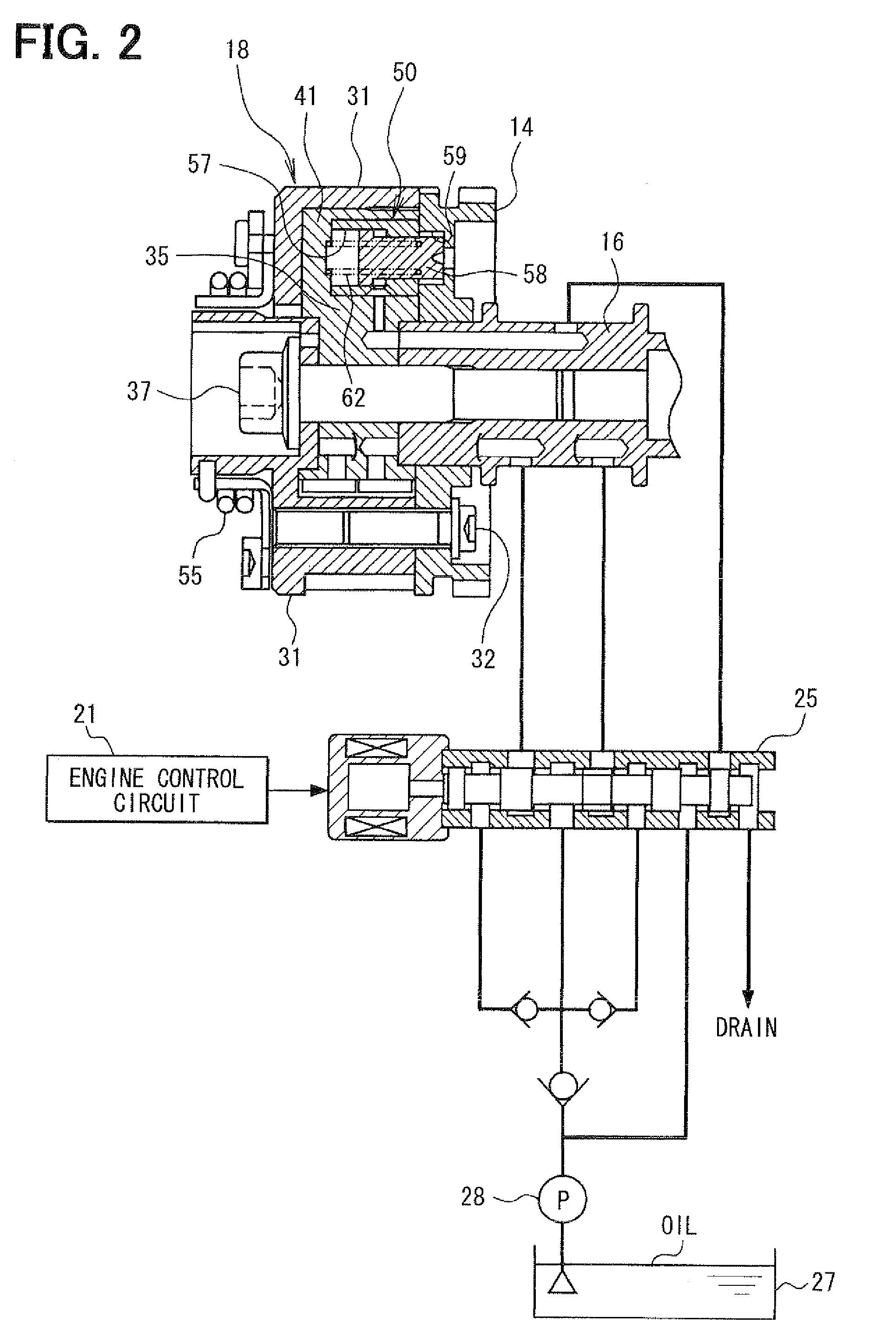
[0072]In the present embodiment 2, at step 117, when it is determined that the VCT phase has passed through the intermediate lock phase, and when it is determined to be an abnormal condition in which the lock pin 58 is not normally projected, the processing proceeds to subsequent step 118. At step 118, a driver is warned about an abnormal condition promptly by lighting of the warning lamp 70 and / or ...

third embodiment

[0074]Subsequently, a third embodiment will be described with reference to FIGS. 9, 10. Description of the same portion as that of the first embodiment will be omitted or simplified, and a different portion from the first embodiment will be described. In the present third embodiment, a provisional learning operation is performed. In the provisional learning operation, when a lock request occurs in a period in which learning of the reference phase is not completed, one phase is selected from the most retarded phase, the most advanced phase, and the intermediate lock phase, and the selected phase is learned as a provisional reference phase. In this manner, when a lock request occurs before completion of learning of the reference phase, one phase is selected as a provisional reference phase from the most retarded phase, the most advanced phase, and the intermediate lock phase. The provisional reference phase is the easiest to be learned or on the most safety side. Thus, the VCT phase c...


PUM


Abstract

A control device projects a lock pin to lock a VCT phase in an intermediate lock phase when a lock request occurs. A learning unit learns one of a most retarded phase, a most advanced phase, and an intermediate lock phase, as a reference phase. A control unit sets a target phase according to the reference phase and controls the control device. A monitor unit determines that the VCT phase has passed through the intermediate lock phase when the lock request occurs before completion of learning of the reference phase, and when a change in the VCT phase becomes greater than a threshold. The threshold is set to be greater than a sum of i) a design value of a phase difference between the intermediate lock phase and one of the most retarded phase and the most advanced phase and ii) a range of a product variation of the phase difference.

Description

CROSS REFERENCE TO RELATED APPLICATIONS[0001]This application is based on and incorporates herein by reference Japanese Patent Application No. 2009-155846 filed on Jun. 30, 2009.FIELD OF THE INVENTION[0002]The present invention relates to a variable valve timing control apparatus for controlling a variable valve timing device for an internal combustion engine, the variable valve timing device having an intermediate lock mechanism configured to lock a rotation phase (henceforth “VCT phase”) of a camshaft relative to a crankshaft of the internal combustion engine in an intermediate lock phase, which is located between a most retarded phase and a most advanced phase in a controllable range. The present invention relates to a method for controlling a variable valve timing device.BACKGROUND OF THE INVENTION[0003]Conventionally, each of Japanese unexamined patent application publication 9-324613 (corresponding to U.S. Pat. No. 5,738,056) and Japanese unexamined patent application publicat...

Claims


Application Information

Patent Timeline
IPC IPC(8): F02D41/00F01L1/34B60Q1/00
CPCF01L1/022F01L1/3442F01L2001/0537F01L2001/3443F01L2001/34463F01L2001/34469Y02T10/42F01L2001/34483F01L2800/01F02D41/0002F02D41/2464F02D41/263F02D2041/001F01L2001/34476Y02T10/40
Inventor WADA, MINORUINOUE, MASAOMI
Owner DENSO CORP
Why Eureka
Try Eureka