System for converting charge into voltage and method for controlling this system

a voltage conversion and voltage technology, applied in the field of charge conversion, can solve the problems of limited passband gain, long and complex research, and high energy consumption, and achieve the effects of high parasitic capacitance, high equivalent capacitance, and significant readout tim

Inactive Publication Date: 2011-01-06
COMMISSARIAT A LENERGIE ATOMIQUE ET AUX ENERGIES ALTERNATIVES
View PDF6 Cites 3 Cited by
  • Summary
  • Abstract
  • Description
  • Claims
  • Application Information

AI Technical Summary

Benefits of technology

[0066]In other words, prior art imaging matrix readout circuits commonly include charge conversion devices at the end of each column of the matrix in order to convert sequentially the electrical charges produced by the unitary detection elements, or pixels, of the column. In fact, prior art charge conversion devices remain constantly connected to the column buses through which the charges from the pixels pass. Said column buses commonly have very high parasitic capacitance and the larger the matrix dimensions the bigger this is. This results in a very significant readout time for the charges produced on account of a high equivalent capacitance. The effect of disconnecting the charge devices from these column buses when establishing the voltages at output from the conversion device is thus a significant increase in establishment speed.

Problems solved by technology

However, increasing the transconductance gm involves using a high-energy consuming amplifier.
Said research is however long and complex in so far as it relates to transistor design.
The passband gain, and therefore the establishment time gain, is limited by the presence of these capacitors.
Likewise, there are still parasitic capacitors at the amplifier input and output which are not connected to the amplifier itself.
It will be noted that the problems disclosed above are posed in the same way in other charge amplification applications.
These problems are also posed in the case of voltage conversion of charge packets from a plurality of input stages sharing a single conversion device.
It will be noted that in this application, the parasitic capacitor connected to the column bus connection is very large, thereby limiting the voltage conversion passband of the incident charge packets.

Method used


Image

  • System for converting charge into voltage and method for controlling this system
  • System for converting charge into voltage and method for controlling this system
  • System for converting charge into voltage and method for controlling this system

Examples


Embodiment Construction

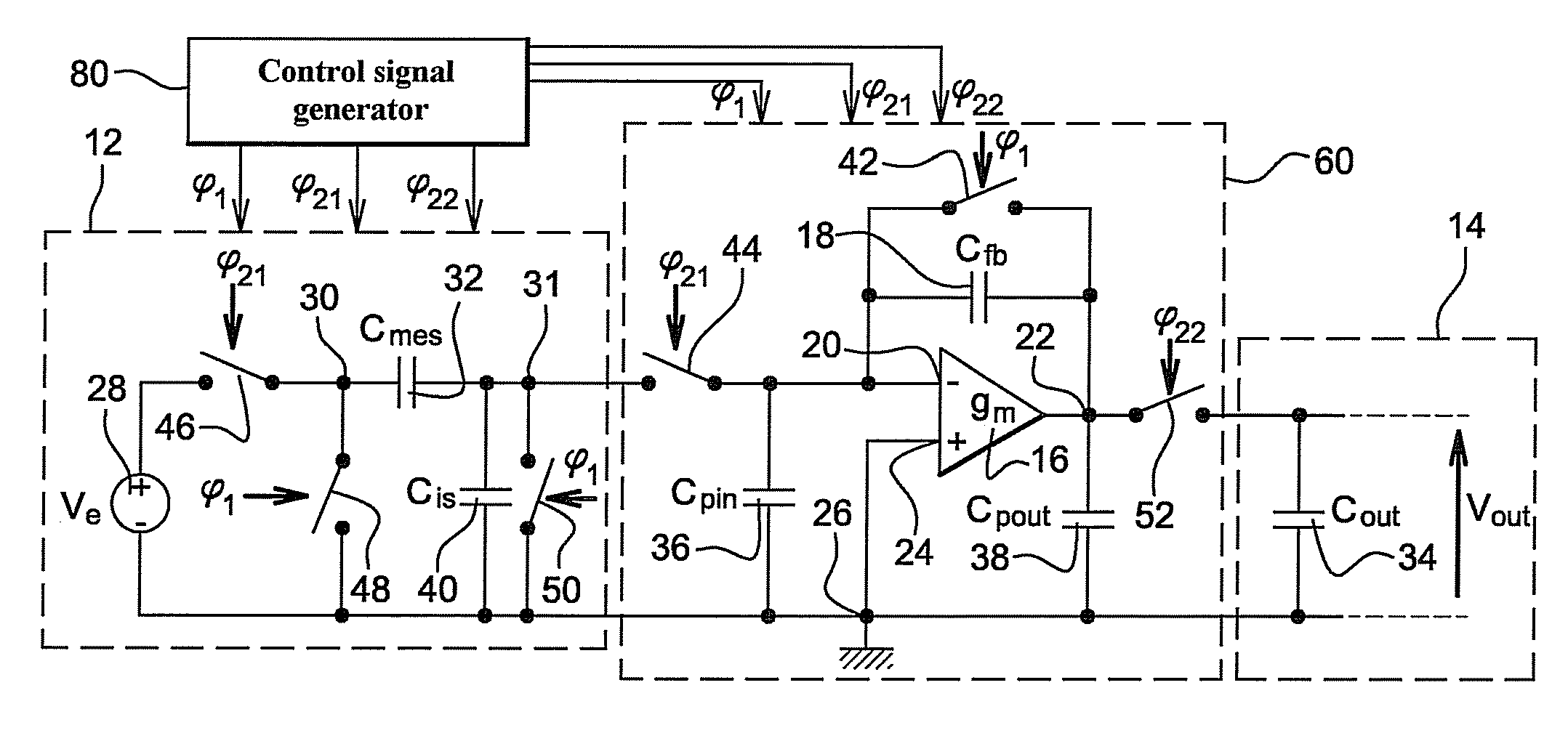
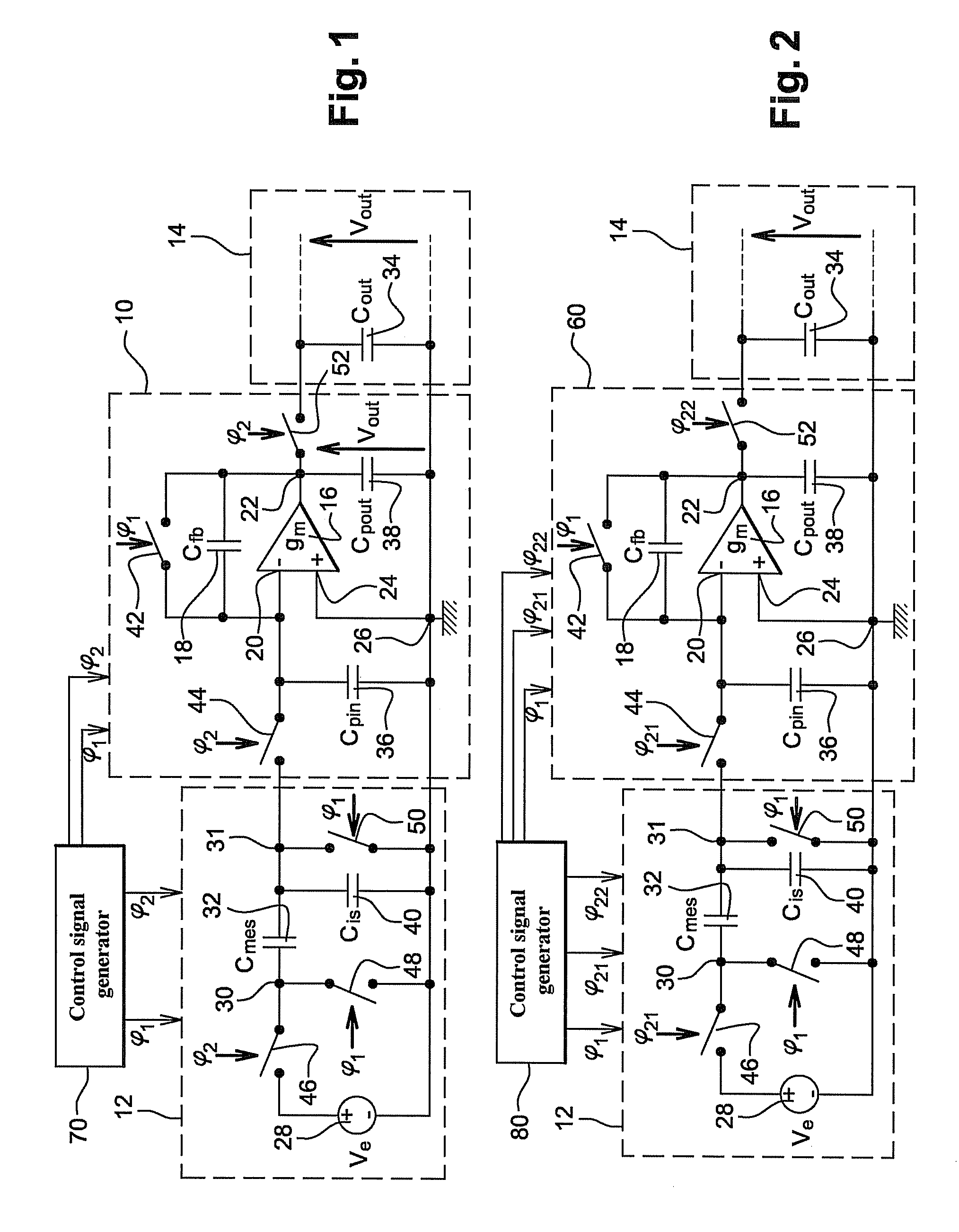
[0083]In FIG. 2, a charge conversion device 60 according to the invention is connected at input to the input stage 12 and at output to the output stage 14. The arrangement in FIG. 2 shows for example the amplification of the voltage Ve or the measurement of variations in the voltage conversion capacitor 32, as has been explained in further detail above.

[0084]In one advantageous application of the invention, the input stage 12 is a micro-electro-mechanical (or MEMS) device or a nano electro-mechanical (or NEMS) device. For example, the input stage 12 is formed of an accelerometer or a gyrometer whereof the capacitor 32, formed of interdigited combs whereof at least one is mobile, varies in time. The charge conversion device 60 is to advantage made using the same MEMS or NEMS technology as the input stage 12.

[0085]The charge conversion device 60 differs from the prior art device 10, described hereinafter in relation to FIG. 1, in that it is associated with a generator 80 of at least t...


PUM


Abstract

The invention relates to controlling a device for converting charge into voltage comprising an amplifier and at least one capacitor mounted in inverse feedback between an input and an output of said amplifier, whereby said amplifier can be connected between at least one input stage, to receive a charge therefrom, and at least one output stage to deliver voltage thereto, said voltage being representative of the charge received at the input, said method comprising at least one phase comprising the voltage conversion of a charge received at the input. According to the invention the conversion phase comprises at least: one first sub-phase during which the amplifier is connected to the input stage and the amplifier is disconnected from the output stage; followed, by a second sub-phase during which the amplifier is disconnected from the input stage and the amplifier is connected to the output stage.

Description

FIELD OF THE INVENTION[0001]The invention relates to the charge conversion field.[0002]To be more specific, the invention relates to a method for controlling a device for converting charges comprising an amplifier and at least one capacitor mounted in inverse feedback between an input and an output of said amplifier, whereby said amplifier can be connected between at least one input stage, to receive a charge therefrom, and at least one output stage to deliver voltage thereto, said voltage being representative of the input charge, said method including at least one phase comprising the voltage conversion of the charge received at the input.PRIOR ART[0003]Charge amplification by means of an operational amplifier with inverse feedback via a capacitor is used in many readout applications, such as for example voltage readout, capacitor readout or charge packet readout.[0004]As is known per se, an operational amplifier has a limited voltage gain in the defined range of its supply voltage...

Claims


Application Information

Patent Timeline
Patent Type & Authority Applications(United States)
IPC IPC(8): H02M11/00
CPCH03F3/005H03F3/72H03F3/087
Inventor AUDEBERT, PATRICKWILLEMIN, JEROME
Owner COMMISSARIAT A LENERGIE ATOMIQUE ET AUX ENERGIES ALTERNATIVES
Why Eureka
Try Eureka