Translumenal apparatus, system, and method

a technology of translumenal tube and apparatus, applied in the field of translumenal tube, system and method, can solve the problems of severe cardiovascular problems, mitral valve not acting, prolapse or regurgitation of mitral valve,

Inactive Publication Date: 2011-01-06
BOSTON SCI SCIMED INC
View PDF22 Cites 15 Cited by
  • Summary
  • Abstract
  • Description
  • Claims
  • Application Information

AI Technical Summary

Problems solved by technology

There are, however, numerous conditions that can cause the mitral valve to not act as a one-way valve.
For example, deficiency or degeneration of one or more of the mitral valve structures may result in dysfunction of the m

Method used


Image

  • Translumenal apparatus, system, and method
  • Translumenal apparatus, system, and method
  • Translumenal apparatus, system, and method

Examples


Embodiment Construction

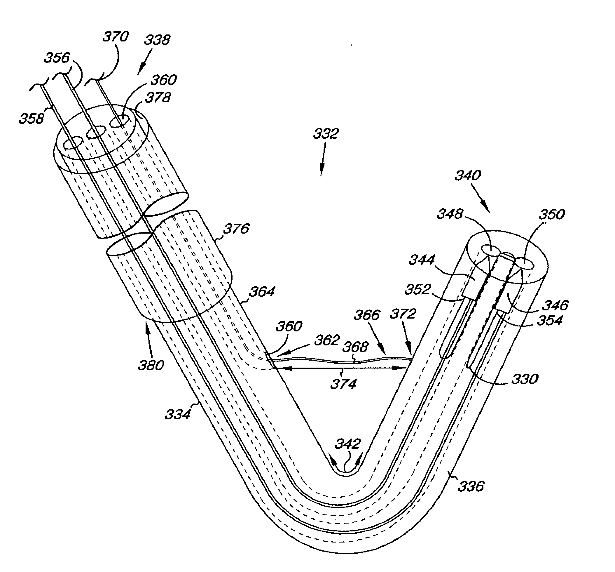
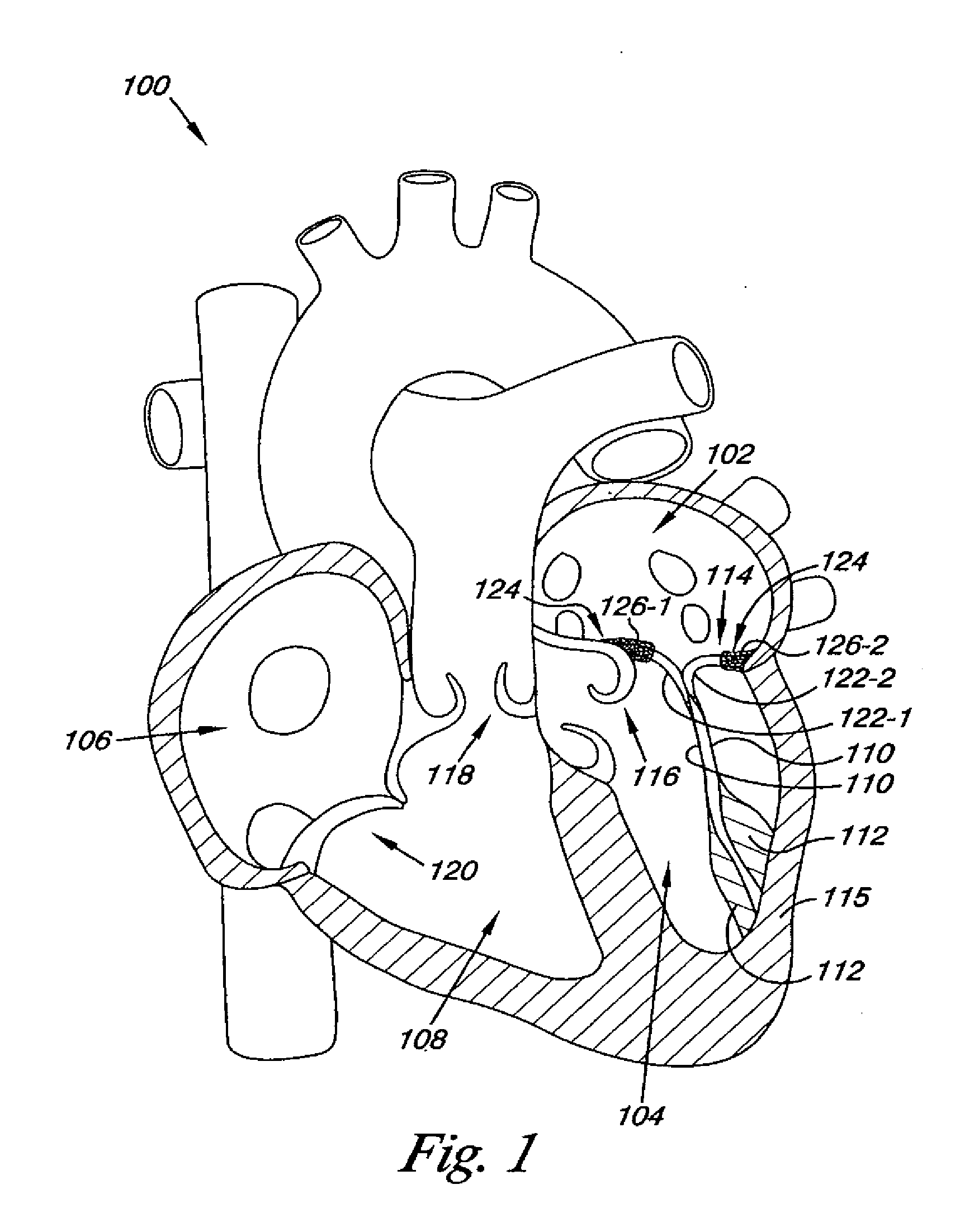
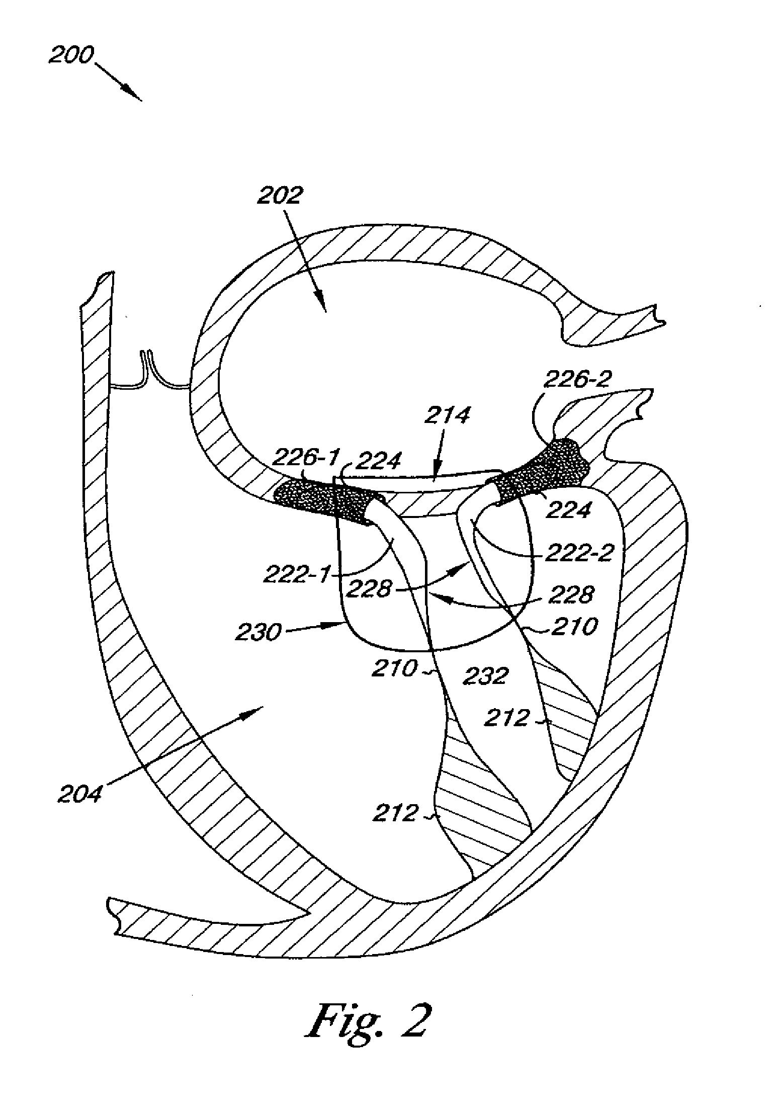
Embodiments of the present invention are directed to methods, apparatus, and systems for helping to improve heart valve function. As discussed herein, improving heart valve function can be accomplished by altering the configuration of the heart valve according to various embodiments of the invention. For example, altering the configuration of the heart valve can be accomplished through the use of a cord delivered into the heart by a delivery catheter. The cord can be positioned relative the heart valve in such a way that by manipulating aspects of the cord (e.g., its length) the configuration of the heart valve can be alter so as to improve the heart valve function. These and other embodiments of the present invention are discussed herein.

The figures herein follow a numbering convention in which the first digit or digits correspond to the drawing figure number and the remaining digits identify an element or component in the drawing. Similar elements or components between different f...


PUM


Abstract

Methods, apparatus, and systems for altering the configuration of a heart valve. Methods, apparatus, and systems include the use of a cord delivered into the heart by a delivery catheter that can be manipulated by a receiving catheter so as to improve the heart valve function.

Description

FIELD OF THE INVENTION The present invention relates generally to apparatus, systems, and methods for use in a heart, more particularly to apparatus, systems, and methods for improving the function of a heart valve.BACKGROUND The human heart is divided into four chambers. These four chambers include the right atrium and the right ventricle, and the left atrium and the left ventricle. The heart contracts rhythmically under stimulation of electrical currents to move blood through the chambers of the heart and the remainder of the cardiovascular system.Blood in the heart is kept flowing in a unidirectional manner through the cardiovascular system by a system of four one-way valves. As the heart cycles the valves open and close to allow blood to move one-way through the heart chambers.The heart valves differ significantly in structure. For example, the ventricles are separated from the atria by valves that, in addition to the leaflets, have thin but strong cords of fibrous tissue. Calle...

Claims


Application Information

Patent Timeline
IPC IPC(8): A61F2/24
CPCA61B17/00234A61B17/0469A61B17/0482A61B2017/00243A61F2/2457A61B2017/0472A61B2017/06057A61F2/2445A61B2017/0409
Inventor SOGARD, DAVID J.HARRISON, KENT D.RICHARDSON, LEONARD B.
Owner BOSTON SCI SCIMED INC
Why Eureka
Try Eureka