
Interference prevention control device of work machine

a control device and work machine technology, applied in mechanical machines/dredgers, analogue processes for specific applications, instruments, etc., can solve problems such as interference with work equipment, difficulty in preventing interference prevention control of work equipment while the cab is moving, etc., to improve work efficiency, prevent interference between the tool of work equipment and the cab, and improve work efficiency

Inactive Publication Date: 2011-01-06
CATEPILLAR SARL
View PDF3 Cites 13 Cited by
  • Summary
  • Abstract
  • Description
  • Claims
  • Application Information

AI Technical Summary

Benefits of technology

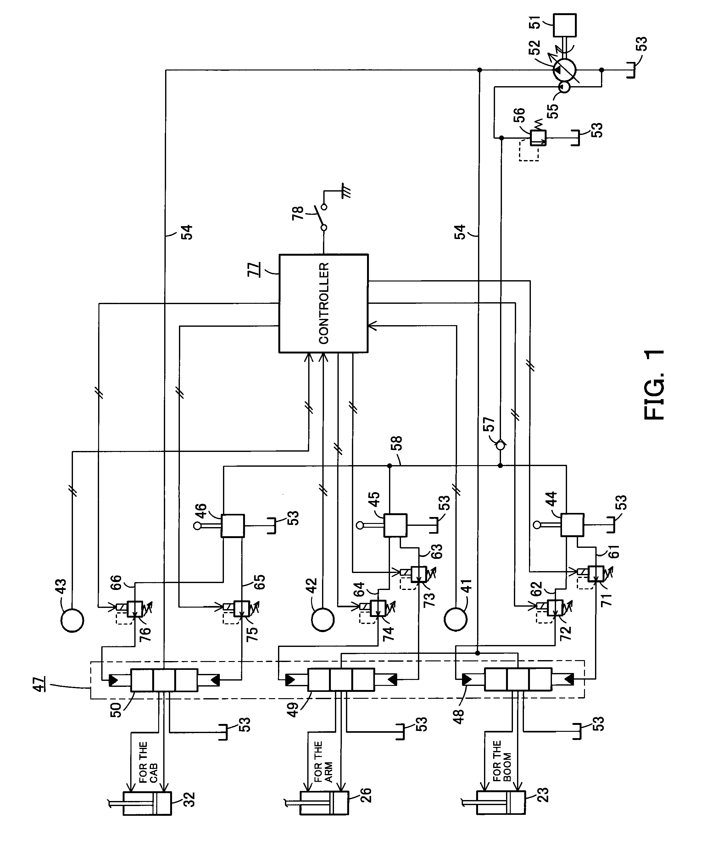
The present invention provides an interference prevention control device for a work machine that can prevent interference between the cab and the work equipment, regardless of whether the cab or the work equipment is moving. This improves work efficiency and prevents damage to the work equipment. The device includes a cab position sensor, a tool position sensor, a limiting means, and a controller. The controller determines the position of the cab and the work equipment, and predicts the future movement of the work equipment based on the position and speed of the cab. The limiting means then controls the movement of the actuator to prevent interference between the predicted positions of the cab and the work equipment. The device can be used with hydraulic actuators and is particularly effective in preventing interference between the tool and the cab.

Problems solved by technology

As the interference prevention control described above adjusts the interference prevention range after actually ascertaining the distance moved by the cab, it is difficult to perform interference prevention control of the work equipment while the cab is moving.
In addition, moving the cab while the work equipment is in operation may result in interference with the work equipment.

Method used


Image

  • Interference prevention control device of work machine
  • Interference prevention control device of work machine
  • Interference prevention control device of work machine

Examples


Embodiment Construction

[0019]Next, the present invention is explained in detail hereunder, referring to an embodiment thereof shown in the attached drawings.

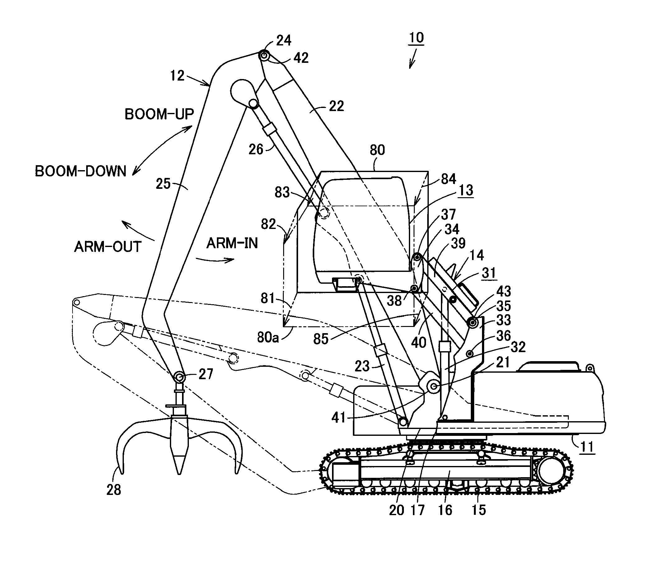
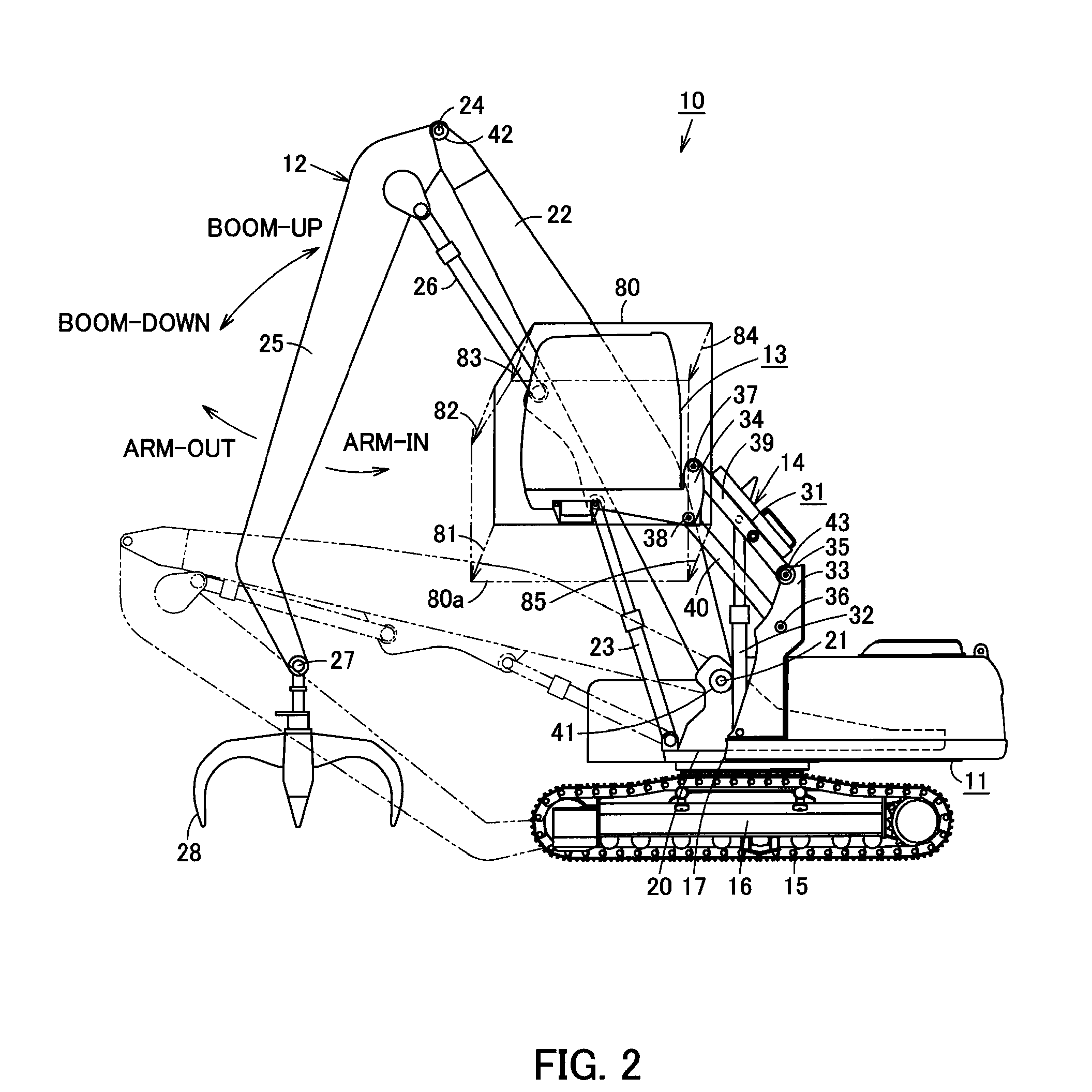
[0020]FIG. 2 illustrates a work machine 10. A front work equipment 12 serving as a work equipment is mounted on the machine body 11 of the work machine 10. At a side of the front work equipment 12, a cab 13 is mounted on the machine body 11 so as to be capable of being lifted above and lowered towards the machine body 11. A cab moving device 14 for lifting and lowering the cab 13 is provided between the cab 13 and the machine body 11. The machine body 11 includes a lower structure 16 equipped with crawler belts 15, and an upper structure 17 rotatably mounted on the lower structure 16.

[0021]The front work equipment 12, which is mounted on the machine body 11 together with the cab 13, includes a boom 22, the base end of which is pivotally supported at a swiveling frame 20 of the machine body 11 by a shaft and a boom foot pin 21. A boom cylinder 23 is pr...


PUM


Abstract

The present invention provides an interference prevention control device of a work machine, wherein the interference prevention control device is capable of preventing interference between the cab and a tool of the work equipment regardless of whether either one of the cab or the work equipment is moved while the other is being operated, and thereby improving operation efficiency of the work machine. With regard to a work machine provided with a movable cab, a cab position sensor for detecting a cab position, as well as a boom angle sensor and an arm angle sensor for detecting a position of a tool at the distal end of the work equipment, are connected to a controller. Solenoid-operated directional control valves for limiting the movement of a boom cylinder and an arm cylinder for operating the work equipment are disposed in pressure passages of a pilot-operated control valve, and the solenoids of the solenoid-operated directional control valves are connected to the controller. The controller computes moving vectors based on the position of the cab detected by the cab position sensor and the moving speed of the cab determined by differentiation, predicts the cab position where the cab should be after a prescribed time, and controls the boom cylinder and the arm cylinder by means of the solenoid-operated directional control valves so as to prevent interference between the predicted cab position and the tool position.

Description

CROSS REFERENCE TO PRIOR APPLICATIONS[0001]This application is a U.S. National Phase application under 35 U.S.C. §371 of International Application No. PCT / JP2009 / 050933, filed on Jan. 22, 2009 and claims benefit of priority to Japanese Patent Application No. 2008-038649, filed on Feb. 20, 2008. The International Application was published in Japanese on Aug. 27, 2009 as WO 2009 / 104449 A1 under PCT Article 21(2). All of these applications are herein incorporated by reference.TECHNICAL FIELD[0002]The present invention relates to an interference prevention control device of a work machine provided with a cab and a work equipment mounted on the machine body in such a manner that the cab and the work equipment are capable of moving independently of each other.BACKGROUND ART[0003]With regard to a work machine provided with a cab and a work equipment mounted on the machine body in such a manner that the cab and the work equipment are capable of moving independently of each other, convention...

Claims


Application Information

Patent Timeline
Patent Type & Authority Applications(United States)
IPC IPC(8): G06F7/00
CPCE02F3/43E02F9/24E02F9/166
Inventor MUROTA, ISAO
Owner CATEPILLAR SARL
Learn More