
Composite downhole tool with reduced slip volume

a technology of tooling and slippage, applied in the direction of fluid removal, sealing/packing, borehole/well accessories, etc., can solve the problems of metal components that require numerous trips in and out, tool damage, and longer milling operation, so as to reduce the volume of metal, improve the uniformity of fracturing, and increase the speed of drilling

Inactive Publication Date: 2011-01-13
WEATHERFORDLAMB
View PDF10 Cites 59 Cited by
  • Summary
  • Abstract
  • Description
  • Claims
  • Application Information

AI Technical Summary

Benefits of technology

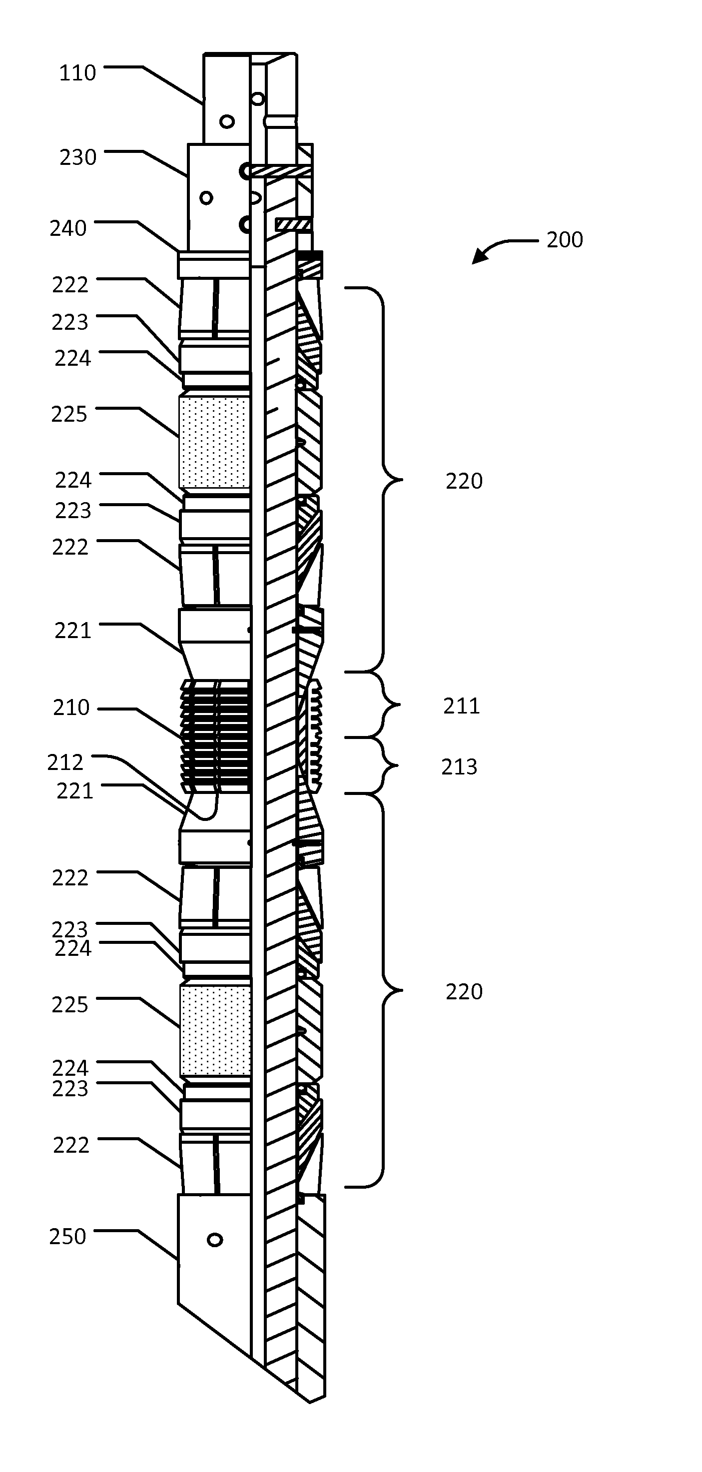
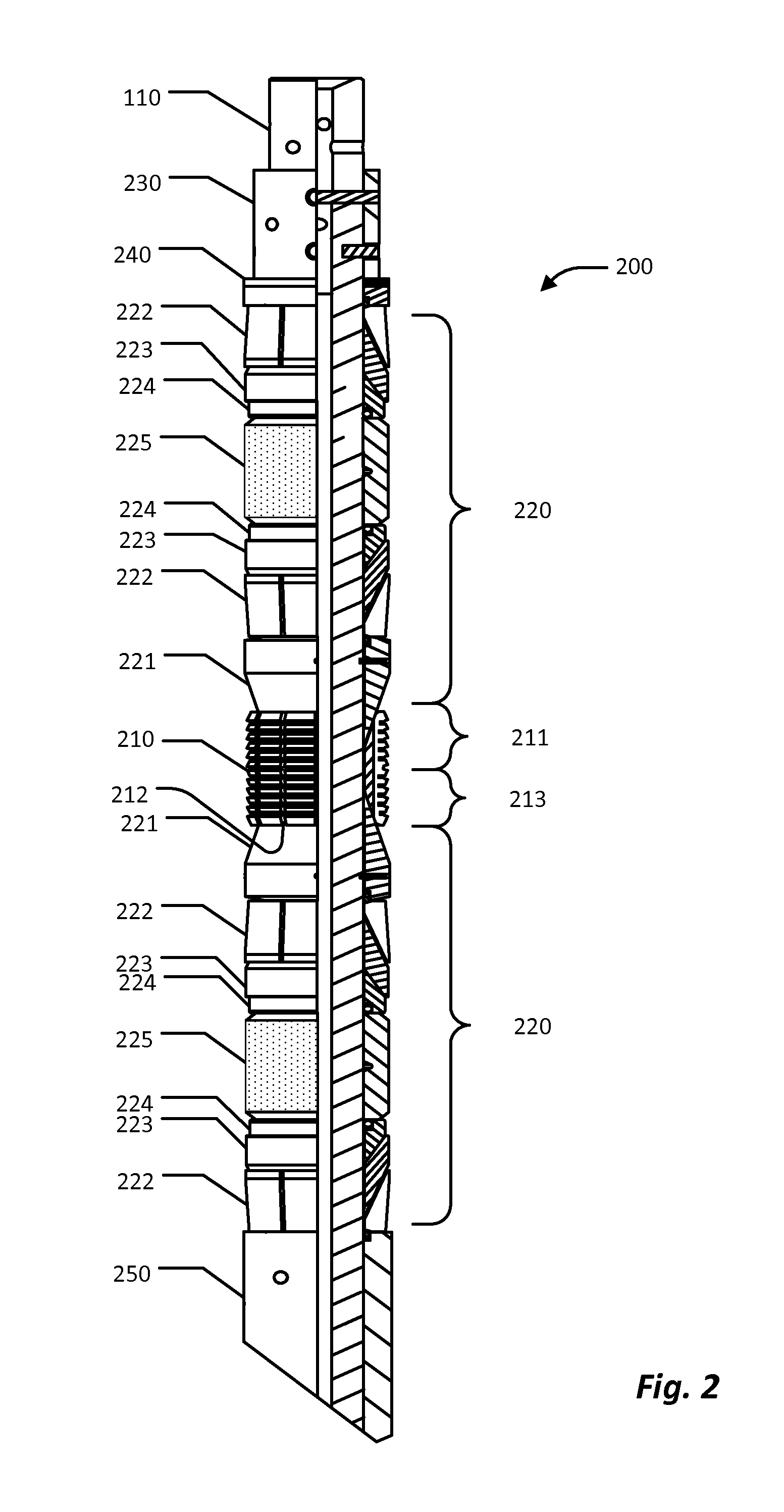
[0008]The conventional two slips of a downhole tool are combined into a single bi-directional slip, thereby reducing the volume of metal and allowing an increased drill up speed. A dual sealing element system, with one sealing element above and one below the bidirectional slip, provides boost forces going through the sealing elements to the slip. In some embodiments, teeth sections of the slip are separated by a substantially flat circumference section for placing a band around the slip to improve fracturing uniformity. The teeth sections can have any of a variety of configurations, including orientations axially away from the central portion of the slip and orientations axially toward the central portion of the slip.

Problems solved by technology

One problem associated with conventional element systems of downhole tools arises when the tool is no longer needed to seal an annulus and must be removed from the wellbore.
Rather than de-actuate the tool and bring it to the surface of the well, the tool is typically destroyed with a rotating milling or drilling device.
The more metal parts making up the tool, the longer the milling operation takes.
Metallic components also typically require numerous trips in and out of the wellbore to replace worn out mills or drill bits.

Method used


Image

  • Composite downhole tool with reduced slip volume
  • Composite downhole tool with reduced slip volume
  • Composite downhole tool with reduced slip volume

Examples


Embodiment Construction

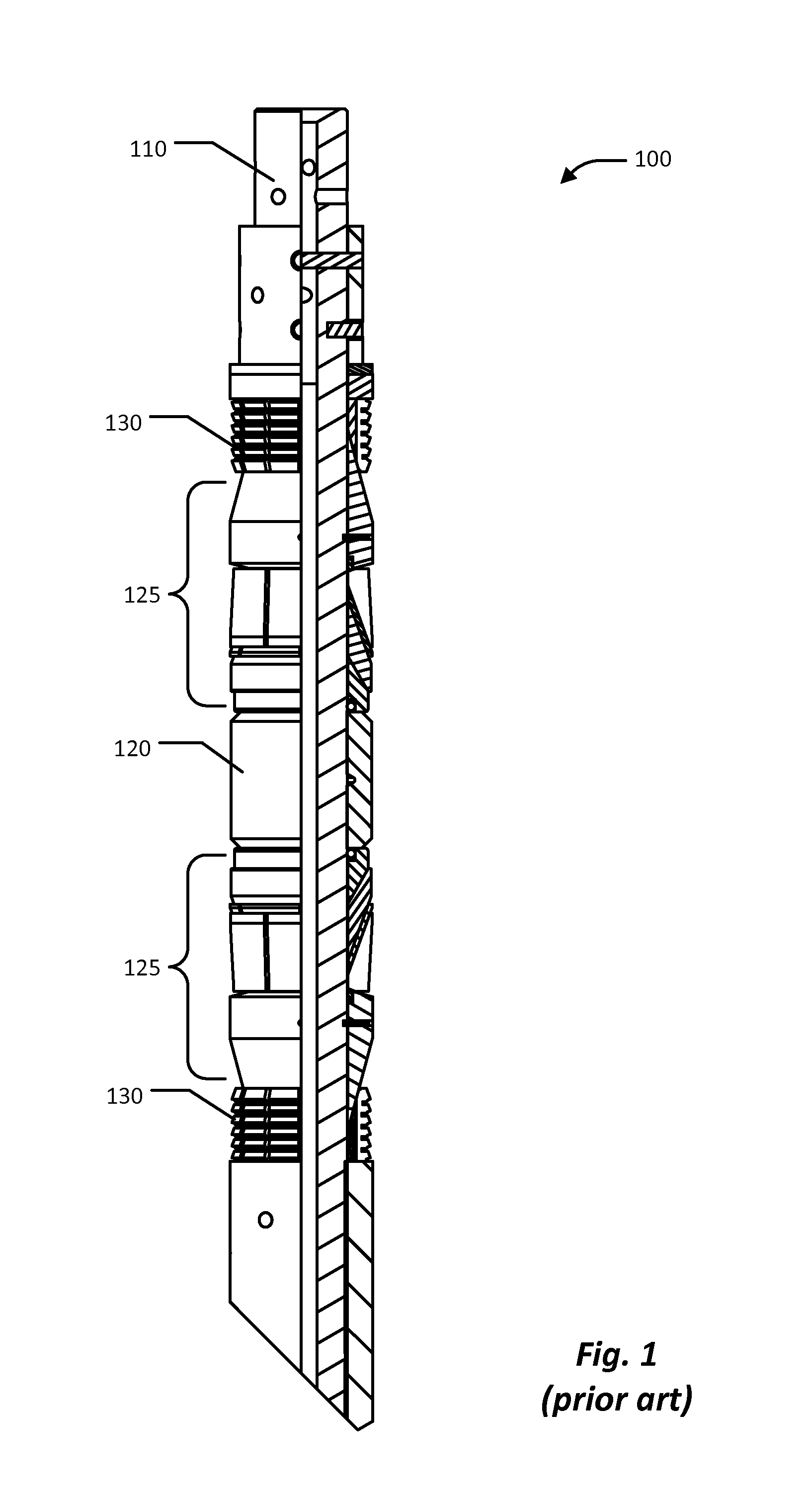
[0015]FIG. 1 is a cutaway view of a conventional bridge plug 100 according to the prior art. The bridge plug 100 comprises a mandrel 110, about which are disposed various elements, which are typically formed of metal, but can be made of a composite material, such as is described in U.S. Pat. No. 7,124,831, which is incorporated herein by reference in its entirety for all purposes. Even when most of the bridge plug 100 is made of composite materials, the two slips 130 are typically made of metal, such as a ductile cast iron.

[0016]As shown in FIG. 1, a sealing member 120 and other related elements 125 are disposed about the mandrel 110. Axial force through the slips 130 and the other elements 125 compress the sealing member 120, causing it to expand and to seal with the surrounding tubular (not shown). The two slips 130, oriented opposite to each other, expand to engage with the surrounding tubular and help retain the downhole tool in place in the wellbore. Boost forces from the seali...


PUM


Abstract

A single bidirectional slip for a downhole tool reduces the volume of metal and allows an increased drill up speed. A dual sealing element system, with one sealing element above and one below the bi-directional slip, provides boost forces going through the sealing elements to the slip. The wickers of the slip can be separated by a substantially flat circumference section for placing a band around the slip to improve fracturing uniformity. The wickers can have any of a variety of configurations, including orientations axially away from the central portion of the slip and orientations axially toward the central portion of the slip.

Description

TECHNICAL FIELD[0001]The present invention relates to the field of downhole tools, and in particular to downhole tools such as bridge plugs, frac-plugs, and packers.BACKGROUND ART[0002]An oil or gas well includes a wellbore extending into a well to some depth below the surface. Typically, the wellbore is lined with tubulars or casing to strengthen the walls of the borehole. To strengthen the walls of the borehole further, the annular area formed between the casing and the borehole is typically filled with cement to set the casing permanently in the wellbore. Perforating the casing allows production fluid to enter the wellbore and flow to the surface of the well.[0003]Downhole tools with sealing elements are placed within the wellbore to isolate the production fluid or to manage production fluid flow through the well. For example, a bridge plug or frac-plug placed within the wellbore can isolate upper and lower sections of production zones. Bridge plugs and frac-plugs create a pressu...

Claims


Application Information

Patent Timeline
IPC IPC(8): E21B33/129E21B33/12E21B33/128E21B23/06
CPCE21B33/134E21B33/1293
Inventor LEMBCKE, JEFFREY
Owner WEATHERFORDLAMB
Learn More