Flexible Flat Panel Display

Active Publication Date: 2011-01-13
AU OPTRONICS CORP
View PDF11 Cites 12 Cited by
  • Summary
  • Abstract
  • Description
  • Claims
  • Application Information

AI Technical Summary

Benefits of technology

[0013]The optical film is disposed between the display panel and the light source module. The optical film has a first surface and a second surface which are opposite to each other. A plurality of platform-shaped optical structures are formed on the first surface, and each platform-shaped optical structure has a flat top surface. A first transparent glue layer and a second transparent glue layer are respectively formed on the light incident surface and the light emergent surface. The flat top surfaces of t

Problems solved by technology

However, one disadvantage of the existing design is that the connection between the display panel and the light source module is not firm enough. FIG. 1 is a cross-sectional view of a conventional flat panel display.
The ray 2A serves as the light source of the display panel 5, while

Method used


Image

  • Flexible Flat Panel Display
  • Flexible Flat Panel Display
  • Flexible Flat Panel Display

Examples


Embodiment Construction

[0029]The present invention provides a flexible flat panel display. In a preferred embodiment, the flexible flat panel display of the present invention can be applied to various flat panel displays such as LCD, ePaper, etc.

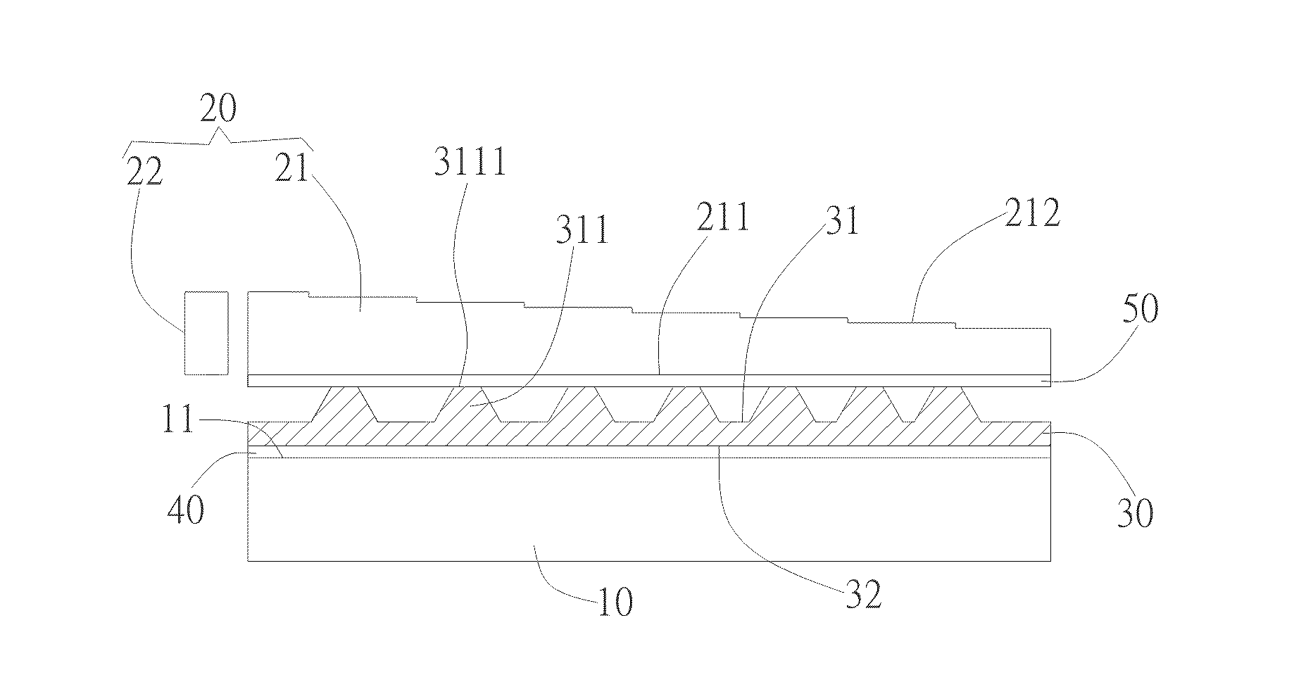
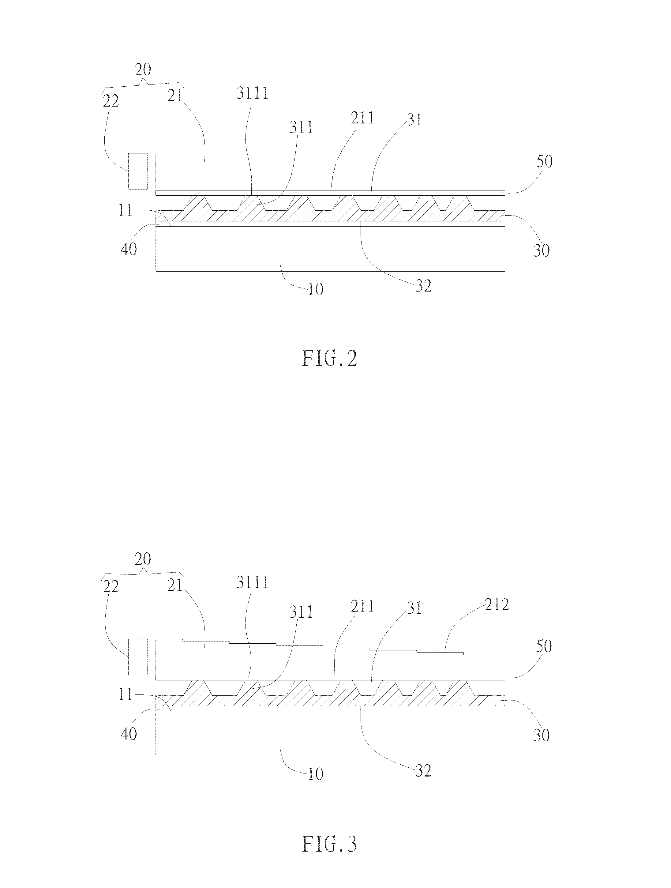
[0030]FIG. 2 is a cross-sectional view of an embodiment of a flexible flat panel display of the present invention. As shown in FIG. 2, the flat panel display includes a display panel 10, a light source module 20, and an optical film 30. In a preferred embodiment, the display panel 10 is an electrophoretic display panel. The common electrophoretic display panel employs numerous micro capsules in transparent liquid media to display images in black and white. Each micro capsule is composed of two hemispheres which are black and white respectively. The rotation of micro capsules are controlled by changing the electric field, so that texts or images can be shown in black and white on the display surface of the electrophoretic display panel under illumination of externa...


PUM


Abstract

A flat panel display is provided. The flat panel display includes a display panel, a light source module and an optical film. The display panel has a light incident surface. The light source module including a light guide plate which has a light emergent surface is disposed parallel to the display panel. The light emergent surface is opposite to the light incident surface. A light emitted from the light source module is transmitted from the light emergent surface to the light incident surface. The optical film is disposed between the display panel and the light source module. The optical film has a first surface and a second surface which are opposite to each other. A plurality of platform-shaped optical structures are formed on the first surface while each of them has a flat top surface. A first transparent glue layer and a second transparent glue layer are respectively formed on the light incident surface and the light emergent surface. The flat top surfaces are glued to one of the first transparent glue layer and the second transparent glue layer while the second surfaces are glued to the other.

Description

[0001]This application claims priority based on a Taiwanese Patent Application No. 098122878, filed on Jul. 7, 2009, the disclosure of which is incorporated herein by reference in its entirety.BACKGROUND OF THE INVENTION[0002]1. Field of the Invention[0003]The present invention relates to a flat panel display (FPD); particularly, the present invention relates to a flat panel display having improved flexibility.[0004]2. Description of the Related Art[0005]To compare with conventional CRT (cathode ray tube) displays, flat panel displays have the advantages of small volume and low power consumption. Hence, as the development tendency of nowadays electronic products focuses on the features of lighter weight, thinner thickness, shorter length and smaller volume, flat panel displays have gradually replaced conventional CRT displays and become the mainstream monitor product of the 21st century.[0006]There are various types of flat panel displays, wherein the LCD (liquid crystal display) wh...

Claims


Application Information

Patent Timeline
IPC IPC(8): G02F1/167F21V8/00G02F1/1677
CPCG02B6/0053G02F2001/133616G02F1/167G02F1/1677G02F1/133616
Inventor CHEN, CHIH-YEN
Owner AU OPTRONICS CORP
Why Eureka
Try Eureka