Cell connection straps for battery cells of a battery pack

a technology of cell connection and battery pack, which is applied in the direction of cell components, batteries, electrical equipment, etc., can solve the problems of li-ion cells posing a safety issue for the end user at these higher currents, several product recalls and/or injuries to end users, and drawbacks of lower capacity cells

Inactive Publication Date: 2011-01-13
WHITE DANIEL J +4
View PDF10 Cites 25 Cited by
  • Summary
  • Abstract
  • Description
  • Claims
  • Application Information

AI Technical Summary

Problems solved by technology

A challenge of using Li-ion cells in a much higher-power environment, such as in a battery pack for supplying power to cordless power tools having current draws at multiple orders or magnitudes in excess of that of a typical cell phone or laptop (0.1-1A)), is that Li-ion cells may pose a safety issue for the end user at these higher currents.
These reactions happen quickly (on the order of seconds) and have caused several recalls of products and / or injuries to end users.
There is a drawback to lower capacity cells, however.
This does not solve the safety problem; however, because when one cell is in parallel with another, it is possible to have a condition where one cell becomes damaged and the energy of the other “good” cell is dumped into the damaged cell.
These welds can be particularly weak when the cell can is constructed with a highly electrically conductive material such as aluminum.
During a drop of the battery pack, as would be seen in a power tool environment, these welds tend to fail.
A common failure mechanism is that the weld joint breaks when it is stressed as the cells move relative to one another within the power tool battery pack.

Method used


Image

  • Cell connection straps for battery cells of a battery pack
  • Cell connection straps for battery cells of a battery pack
  • Cell connection straps for battery cells of a battery pack

Examples


Embodiment Construction

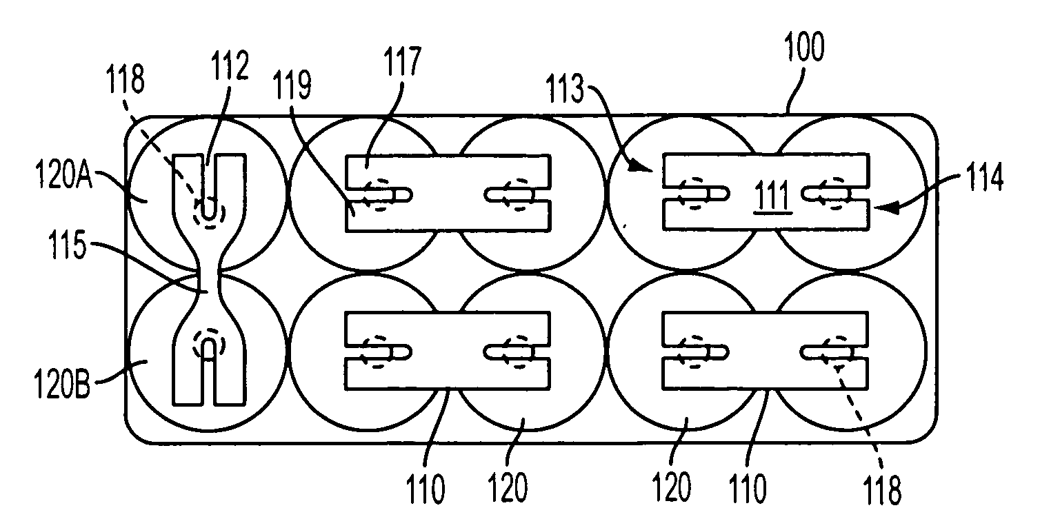
[0027]FIG. 1 is a top view showing cell connection straps within a battery pack that has a pair of serial strings of cells 120 connected in parallel. Power terminal leads are not shown for purposes of clarity, it being understood that a pair of power leads may be connected to cells 120 on an opposite side of the pack 100, in place of a given cell strap 110 between two cells, as is known. In FIG. 1, there is shown only a bottom housing of a battery pack 100 (top housing removed for clarity) containing a plurality of cells 120 in two serial strings that are connected in parallel. This is just an example connection scheme, as battery pack 100 may be configured to have additional cells 120 in series or parallel. The cells 120 may be oriented sideways within the housing of pack 100 instead of upright as shown in FIG. 1.

[0028]In one example, the battery pack 100 may include high power density (mass), Li-ion cells 120, which have a much higher power density as compared to NiMH or NiCd cell...


PUM

PropertyMeasurementUnit
currentsaaaaaaaaaa
current carrying capabilityaaaaaaaaaa
electricallyaaaaaaaaaa

Abstract

A cell connection strap for electrically connecting a pair of adjacent battery cells within a battery pack includes, in one example, a fusible link for preventing a thermal runaway condition from occurring in a cell connected thereto. The strap may include raised features thereon for permitting relative movement between the cells in the pack due to vibration or an impact of the pack from translating stress to welds connecting the straps to the cells. In another example, the body of the cell strap may include slits formed in sides thereof to reduce rigidity of the strap for protecting the welds between strap and cell, and also provides a fusible link capability in the strap for preventing a thermal runaway condition from occurring in a cell connected thereto.

Description

PRIORITY STATEMENT[0001]This application claims the benefit under 35 U.S.C. §119(e) to the following U.S. Provisional Patent Applications: Ser. No. 60 / 731,501, filed Oct. 31, 2005 to Daniel J. White et al. and entitled “FUSE PROTECTION FOR BATTERY PACKS HAVING LI-ION CELLS IN PARALLEL”; and Ser. No. 60 / 836,396, filed Aug. 9, 2006 to Steven J. Phillips et al. and entitled “WELD STRAP IMPROVEMENTS FOR BATTERY CELLS”. The entire contents of each of these provisional applications are hereby incorporated by reference herein.BACKGROUND OF THE INVENTION[0002]1. Field of the Invention[0003]Example embodiments in general relate to battery cell connection straps for electrically connecting battery cells in a battery pack.[0004]2. Description of Related Art[0005]As cordless power tools begin to push new, higher power to density (mass and volume) limits, new battery chemistries are being investigated as a viable power sources for high-power (such as above 18V) cordless power tool applications. ...

Claims


Application Information

Patent Timeline
Patent Type & Authority Applications(United States)
IPC IPC(8): H01M10/50H01M50/503H01M50/51H01M50/583
CPCH01M2/1055H01M2/204H01M2200/106H01M2/348H01M2200/103H01M2/34Y02E60/10H01M50/213H01M50/581H01M50/51H01M50/583H01M50/503
Inventor WHITE, DANIEL J.PHILLIPS, STEVEN J.CASALENA, ADAM M.JOHNSON, ALEXISROBERTS, JR., MICHAEL W.
Owner WHITE DANIEL J
Why Eureka
Try Eureka