Universal serial bus connector
a technology of universal serial bus and connector, which is applied in the direction of coupling device connection, coupling protective earth/shielding arrangement, two-part coupling device, etc., can solve the cost and life of the mold of the first body c and the second body d, and the traditional manufacturing process cannot efficiently assembly the contact portions of the terminals. , to achieve the effect of convenient disposal
- Summary
- Abstract
- Description
- Claims
- Application Information
AI Technical Summary
Benefits of technology
Problems solved by technology
Method used
Image
Examples
first embodiment
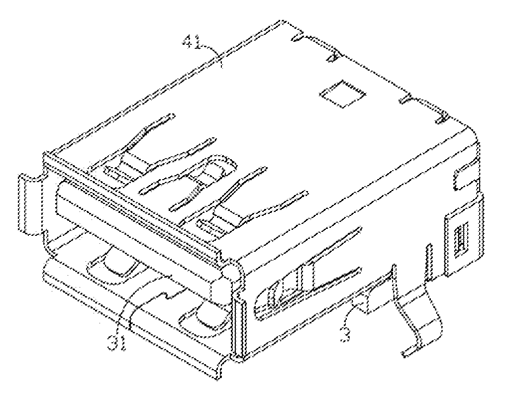
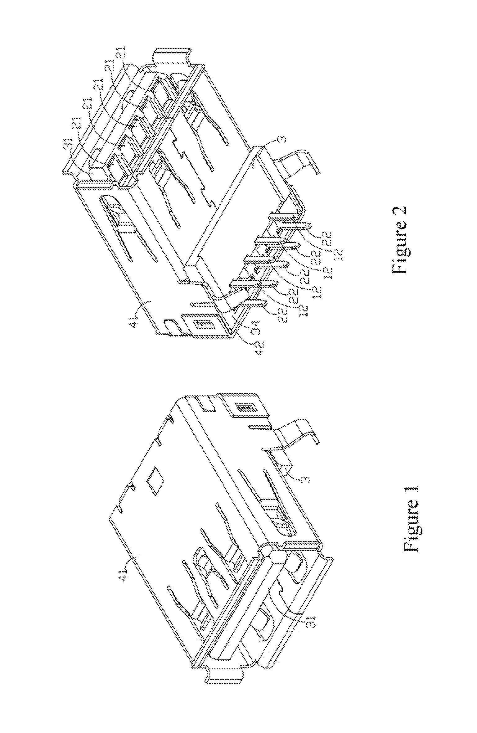
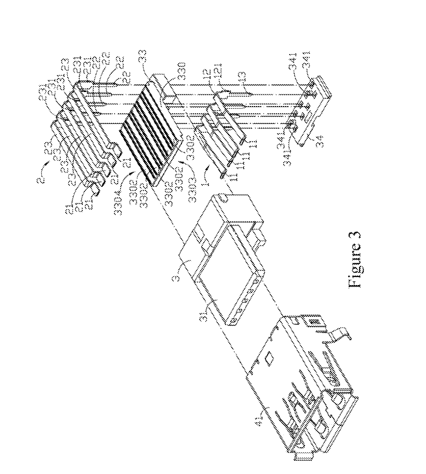
[0036]FIGS. 1 to 4 depict the Universal Serial Bus connector according to the disclosure, i.e., a board end USB 3.0 connector, adapted to be disposed on a print circuit board (not shown) and to communicate the electric signals between a dock connector and the circuit board.
[0037]In the first embodiment of the disclosure, the Universal Serial Bus connector comprises a set of first terminals 1, a set of the second terminal 2, an insulator 3 and a shielding shell 4. The contact portion (11, 21) of each of the first terminal 1 and the second terminal 2 can be respectively connected to the dock connector or a cable end connector (not show). The tail portion (12, 22) of each of the first terminal 1 and the second terminal 2 can be respectively connected to a circuit board (not shown) to form the electric connection. The extended portion (13, 23) of each of the first terminals 1 and the second terminals 2 is connected to the contact portion (11, 21) and the tail portion (12, 22) of each of...
second embodiment
[0047]In the second embodiment, the insulator 3 is made of an insulating material and two tongue portions (31, 31′) respectively extended toward two dock connectors (not shown), and a notch 32 is formed on the insulator 3 away from the tongue portions (31, 31′). The notch 32 of the insulator 3 can accommodate at least one upper cap 33 and at least one lower cap 33′, which are respectively assembled into the insulator 3. The two caps (33, 33′) of the insulator are removably disposed on the insulator 3. The extended portions (13, 13′, 23, 23′) of the first terminals (1, 1′) and the second terminals (2, 2′) are respectively disposed on the caps (33, 33′), and the caps (33, 33′) of the insulator 3 have the first terminal receiving groove (331, 331′) and the second terminal receiving grooves (332, 332′) to accommodate a portion of the extended portions (13, 13′, 23, 23′) of the first terminals (1, 1′) and the second to terminals (2, 2′). The first terminals (1, 1′) and the second termina...
PUM
 Abstract
Description
Claims
Application Information
 - R&D
- Intellectual Property
- Life Sciences
- Materials
- Tech Scout
- Unparalleled Data Quality
- Higher Quality Content
- 60% Fewer Hallucinations
Browse by: Latest US Patents, China's latest patents, Technical Efficacy Thesaurus, Application Domain, Technology Topic, Popular Technical Reports.
© 2025 PatSnap. All rights reserved.Legal|Privacy policy|Modern Slavery Act Transparency Statement|Sitemap|About US| Contact US: help@patsnap.com


