Powerboat rooster tail depressor

a technology of rooster tail and depressor, which is applied in the direction of marine propulsion, special-purpose vessels, vessel construction, etc., can solve the problems of increasing the size exposing military vessels to the enemy, and becoming quite large, so as to reduce the radar signature of the rooster tail and increase the efficiency of the powerboa

Inactive Publication Date: 2011-01-20
M SHIP
View PDF9 Cites 3 Cited by
  • Summary
  • Abstract
  • Description
  • Claims
  • Application Information

AI Technical Summary

Benefits of technology

[0006]It is a primary object of the present invention to alleviate the foregoing concerns. The present invention does so by providing what may be called a “rooster tail depressor” (RTD). It is a rooster-tail-suppressing assembly on the hull that takes the form of a structure (e.g., a canopy) extending rearwardly of the stern and over the powerboat's rooster-tail-producing propulsion discharge. The RTD suppresses the propulsion discharge and thereby the rooster tail in a way that reduces the rooster tail radar signature while increasing powerboat efficiency.
[0008]The RTD recaptures a large amount of energy in the rooster tail that is otherwise lost. Recapturing this energy produces a significant gain in vessel lift, thereby reducing friction drag for a planing craft with an increase in propulsion efficiency. The RTD traps the vertical component of the propulsion discharge for vessel lift, while merely redirecting the horizontal component downward without braking the vessel and thereby reducing its forward velocity.

Problems solved by technology

Such a rooster tail increases in size with vessel speed and can become quite large.
One problem with powerboat rooster tails is that they can expose military vessels to the enemy.
Another problem relates to powerboat efficiency in that a large amount of energy is expended in creating the rooster tail.

Method used


Image

  • Powerboat rooster tail depressor
  • Powerboat rooster tail depressor
  • Powerboat rooster tail depressor

Examples


second embodiment

[0025]FIG. 4a is a diagrammatic elevation view of a canopy 32 on the invention. The canopy 32 is faceted in the sense that it includes a downwardly facing surface 32A having a cross sectional shape in a vertical transverse plane parallel to the X-Y axis that is not continuously curved; it includes multiple line segments or chords instead.

third embodiment

[0026]FIG. 4b is a diagrammatic elevation view of a canopy 33 on the invention. The canopy 33 is curved in the sense that it includes a downwardly facing surface 33A having a cross sectional shape in a vertical transverse plane parallel to the X-Y axis that is continuously curved. The shapes of the canopy 32 and the canopy 33 are functions of the propeller size, number, and location. Other considerations affecting their shapes include construction material and attachment design.

fourth embodiment

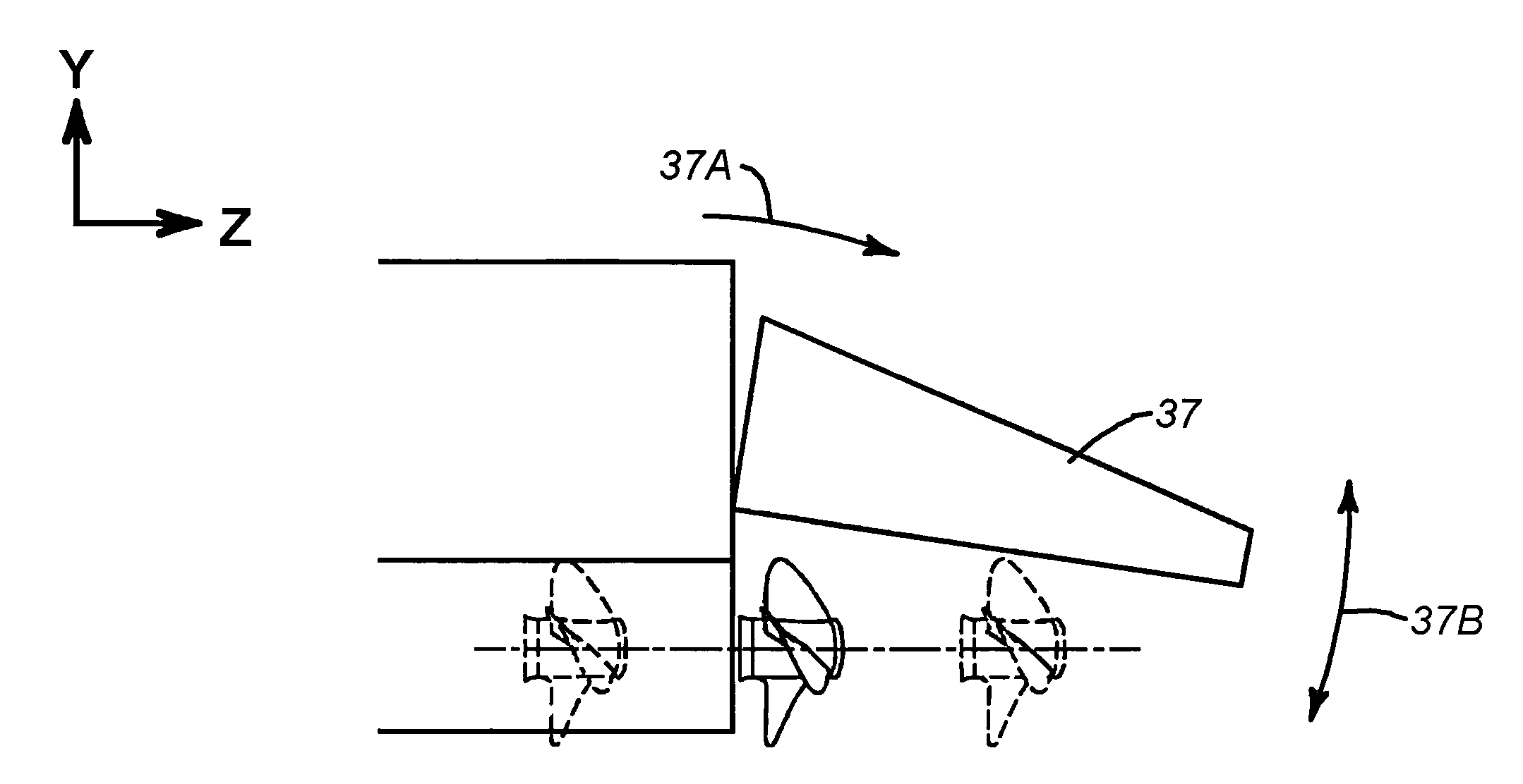
[0027]FIG. 5 is a diagrammatic elevation view of the invention having a canopy 34 with a downwardly facing surface 34A that includes lift-to-drag ratio enhancement steps. The steps are designed to promote separation of the redirected rooster tail from the RTD as soon as possible. That is done to reduce wetted surface area and viscous drag. The steps also convert any forward motion of the propeller wake into thrust.


PUM


Abstract

A powerboat with a rooster tail depressor (RTD) includes a hull, a propulsion subassembly on the hull, and a rooster-tail-suppressing subassembly on the hull. The propulsion subassembly propels the hull forwardly, producing a propulsion discharge that extends rearwardly of the stern. The rooster-tail-suppressing subassembly extends rearwardly of the stern over at least a portion of the propulsion discharge where it functions to suppress the formation of a powerboat rooster tail (e.g., for radar signature reduction and increased propulsion efficiency). Various embodiments include one or more of (i) a canopy having a downwardly facing surface that is arched (either curved or faceted), (ii) lift-to-drag ratio enhancing steps in the downwardly facing surface of the canopy, (iii) a rooster-tail-suppressing subassembly configured to enable articulation of the canopy in yaw and in trim, (iv) a skeg for enhancing maneuverability of the boat hull, and (v) a conveniently removable and / or retractable rooster-tail-suppressing subassembly.

Description

BACKGROUND OF THE INVENTION[0001]1. Technical Field[0002]This invention relates generally to the field of powered watercraft, and more particularly to powerboats, seagoing vessels, and the like that tend to produce a rooster tail when moving forwardly.[0003]2. Description of Related Art[0004]When the hull of a powerboat is driven forward, whether by propellers, water jets, or some other propulsion subassembly on the vessel, the propulsion subassembly often produces what can be called a propulsion discharge. As the hull is propelled forwardly, the propulsion discharge (i.e., water) is forced into the air rearward of the powerboat's stern. The resulting plume of water behind the powerboat is commonly referred to as a “rooster tail” because it reminds one of the tail of a rooster. Such a rooster tail increases in size with vessel speed and can become quite large.[0005]One problem with powerboat rooster tails is that they can expose military vessels to the enemy. The rooster tail can cr...

Claims


Application Information

Patent Timeline
Patent Type & Authority Applications(United States)
IPC IPC(8): B63B1/00
CPCB63B1/08Y02T70/128Y02T70/127B63H5/16Y02T70/10
Inventor ROBINSON, CHARLES W.BURNS, III, WILLIAM F.
Owner M SHIP
Why Eureka
Try Eureka