Plasma Gun and Plasma Gun Deposition System Including the Same

Inactive Publication Date: 2011-01-20
SHIN MEIWA IND CO LTD
View PDF3 Cites 23 Cited by
  • Summary
  • Abstract
  • Description
  • Claims
  • Application Information

AI Technical Summary

Benefits of technology

[0017]In accordance with one exemplary aspect, using the plasma gun and plasma gun deposition system as disclosed herein, it is possible to prevent the metal, having been sputtered at the time of the glo

Problems solved by technology

However, the problem is that when using the composite cathode type plasma gun or the dual type plasma gun, the cathode is sputtered by argon ions (Ar+)

Method used


Image

  • Plasma Gun and Plasma Gun Deposition System Including the Same
  • Plasma Gun and Plasma Gun Deposition System Including the Same
  • Plasma Gun and Plasma Gun Deposition System Including the Same

Examples


embodiment 1

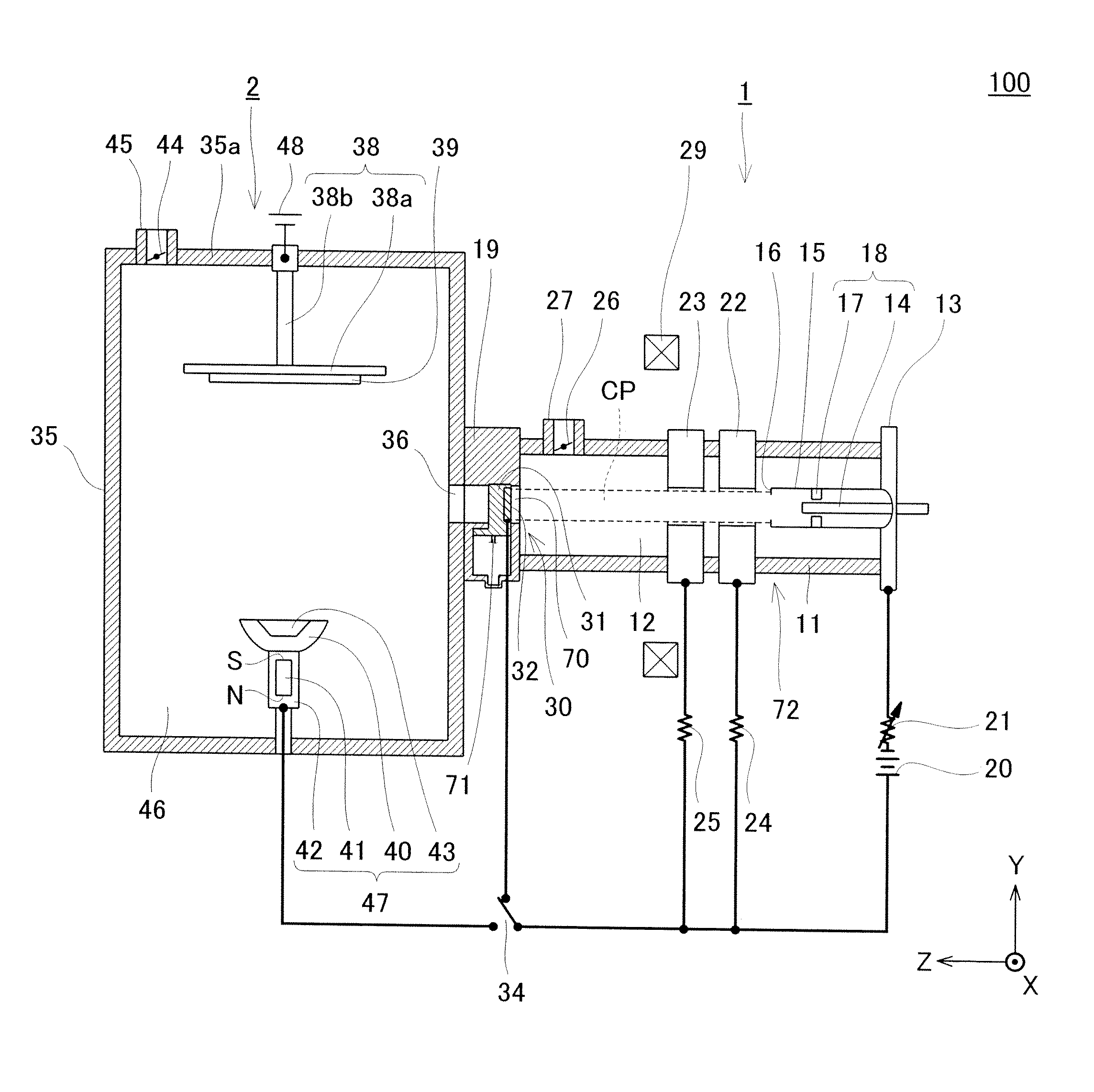
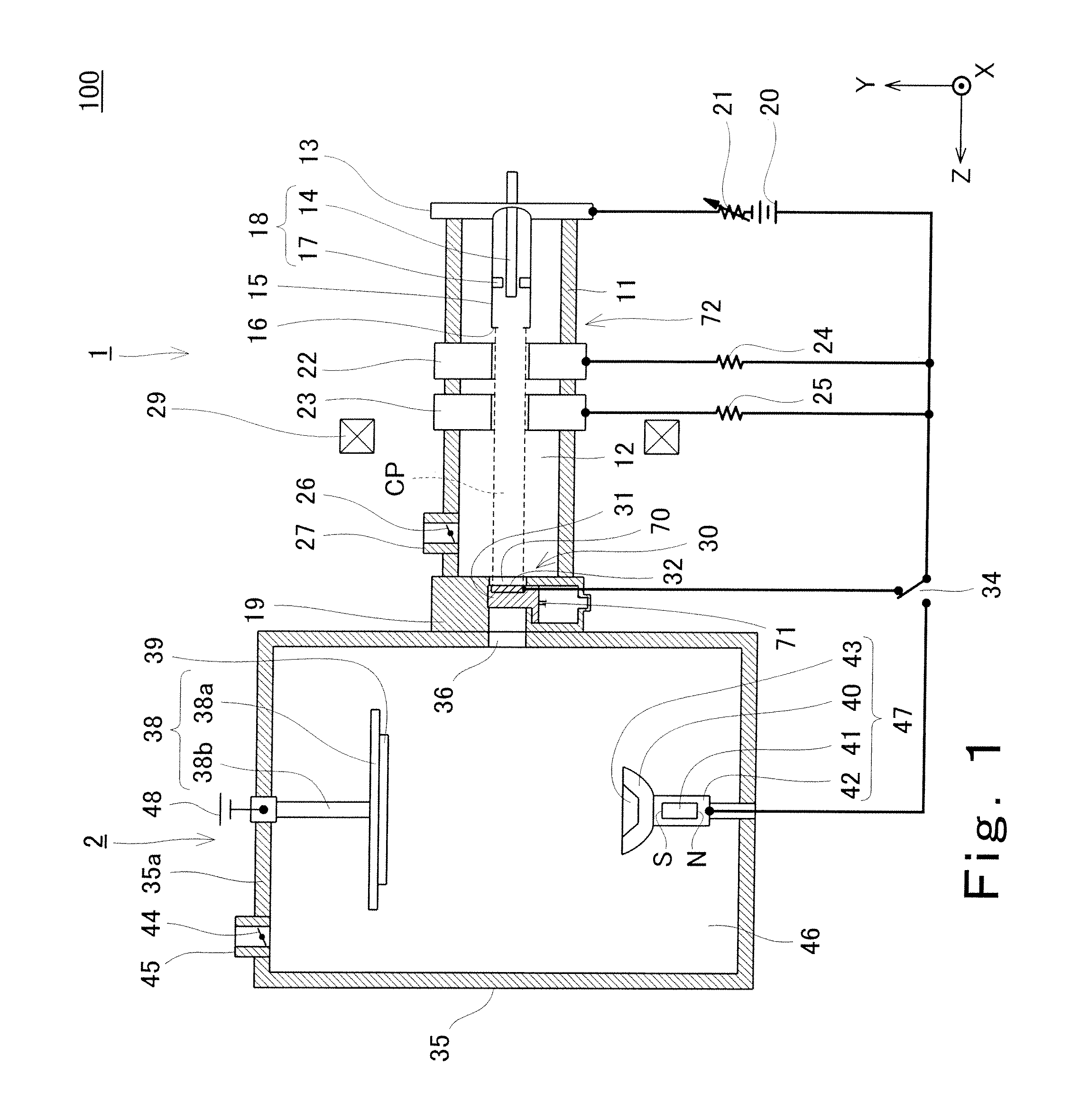
[0027]FIG. 1 is a schematic diagram showing the configuration of a plasma gun deposition system according to Embodiment 1 of the present invention. FIG. 2 is a schematic diagram showing a state where an opening / closing member of a plasma flow-out preventing / allowing device of the plasma gun deposition system shown in FIG. 1 is open.

[0028]First, the configuration of the plasma gun deposition system according to Embodiment 1 will be explained in reference to FIGS. 1 and 2. In the present embodiment, directions in the configuration of the plasma gun deposition system are indicated for convenience by directions of an X-axis, a Y-axis and a Z-axis of a 3-D rectangular coordinate system shown in FIGS. 1 and 2.

[0029]As shown in FIG. 1, a plasma gun deposition system 100 according to Embodiment 1 includes a dual type plasma gun 1 which generates high-density plasma and a deposition chamber 2 in which a film is formed on a substrate by utilizing the plasma generated by the plasma gun 1. The ...

modification example 1

[0050]FIG. 3 is a schematic diagram showing the configuration of a plasma gun deposition system according to Modification Example 1. FIG. 4 is a schematic diagram showing a state where the opening / closing member 31 of the plasma flow-out preventing / allowing device 70 of a plasma gun deposition system 101 shown in FIG. 3 is open. In the following explanation, same reference numbers are used for members similar to or corresponding to the members shown in FIG. 1, and a repetition of the same explanation is avoided.

[0051]As shown in FIG. 3, in the present modification example, the auxiliary anode 32 shown in FIG. 1 is disposed at an intermediate position of the tubular body 11. The auxiliary anode 32 is configured such that in a case where the auxiliary anode 32 receives the plasma generated by the cathode 17, current is not supplied to the magnet coil 29.

[0052]Specifically, the auxiliary anode 32 includes a metal (copper for example) cylindrical anode member 74 disposed coaxially with ...

embodiment 2

[0058]FIG. 5 is a schematic diagram showing the configuration of a plasma gun deposition system 200 according to Embodiment 2 of the present invention. FIG. 6 is a schematic diagram showing a state where the opening / closing member of the plasma flow-out preventing / allowing device of the plasma gun deposition system 200 shown in FIG. 5 is open. In the following explanation, same reference numbers are used for members similar to or corresponding to the members shown in FIG. 1, and a repetition of the same explanation is avoided. Moreover, in the present embodiment, the directions in the configuration of the plasma gun deposition system 200 are indicated for convenience by the directions of the X-axis, Y-axis and Z-axis of the 3-D rectangular coordinate system shown in FIGS. 5 and 6.

[0059]As shown in FIG. 5, the plasma gun deposition system 200 according to Embodiment 2 has substantially a cross shape on a Y-Z plane and includes the plasma gun 1, a cylindrical nonmagnetic (stainless st...


PUM


Abstract

A plasma gun of the present invention includes: a container having a plasma outflow opening; a cathode (18) which is disposed inside the container to generate plasma by discharge; an auxiliary anode which is disposed to be able to be located between the plasma outflow opening and the cathode and is able to receive the plasma generated by the cathode; an exhaust valve for exhausting air from and sealing an inside of the container; and a plasma flow-out preventing/allowing device which prevents the plasma, having been generated by the discharge of the cathode, from flowing out from the plasma outflow opening and allows the plasma to flow out from the plasma.

Description

TECHNICAL FIELD [0001]The present invention relates to a plasma gun and a plasma gun deposition system including the same.BACKGROUND ART [0002]A plasma deposition system is an apparatus which forms a film by using plasma, generated from a plasma gun, as an ion source. Known plasma guns used in such plasma deposition systems are composite cathode type plasma guns, pressure gradient type plasma guns and dual type plasma guns that are a combination of the composite cathode type plasma gun and the pressure gradient type plasma gun (see Japanese Patent Publication No. 2921874 (Patent Document 1) for example). Generally, these plasma guns generate plasma using an argon (Ar) gas as a carrier gas. To generate the plasma, glow discharge is carried out by a cathode of the plasma gun, and then shifts to arc discharge. However, the problem is that when using the composite cathode type plasma gun or the dual type plasma gun, the cathode is sputtered by argon ions (Ar+) during the glow discharge,...

Claims


Application Information

Patent Timeline
IPC IPC(8): C23C14/46
CPCC23C14/32H05H1/54H01J37/32431H05H1/24
Inventor MARUNAKA, MASAOTSUCHIYA, TAKAYUKITERAKURA, ATSUHIRO
Owner SHIN MEIWA IND CO LTD
Why Eureka
Try Eureka