Wind turbine generator and method for constructing the same

Inactive Publication Date: 2011-01-20
MITSUBISHI HEAVY IND LTD
View PDF3 Cites 24 Cited by
  • Summary
  • Abstract
  • Description
  • Claims
  • Application Information

AI Technical Summary

Benefits of technology

[0023]Because the method for constructing a wind turbine generator includes the step of attaching the components of the yaw system to the topmost pillar member of the tower, the step of building the tower by coupling the pillar members together, and the step of attaching the nacelle to the top end of the tower, the weight of the nacelle is reduced by that of the yaw system relocated to the pillar-member side. Accordingly, a load imposed on a crane is reduced, so that a general-purpose crane can be used to carry out a procedure for hoisting the nacelle with the crane and attaching it to the top

Problems solved by technology

The recent trend is that the size (output power) of wind turbine generators has been increasing, and the increased size of wind turbine generators has resulted in increased nacelle weight.
Recently, therefore, existing general-purpose construction c

Method used


Image

  • Wind turbine generator and method for constructing the same
  • Wind turbine generator and method for constructing the same
  • Wind turbine generator and method for constructing the same

Examples


Embodiment Construction

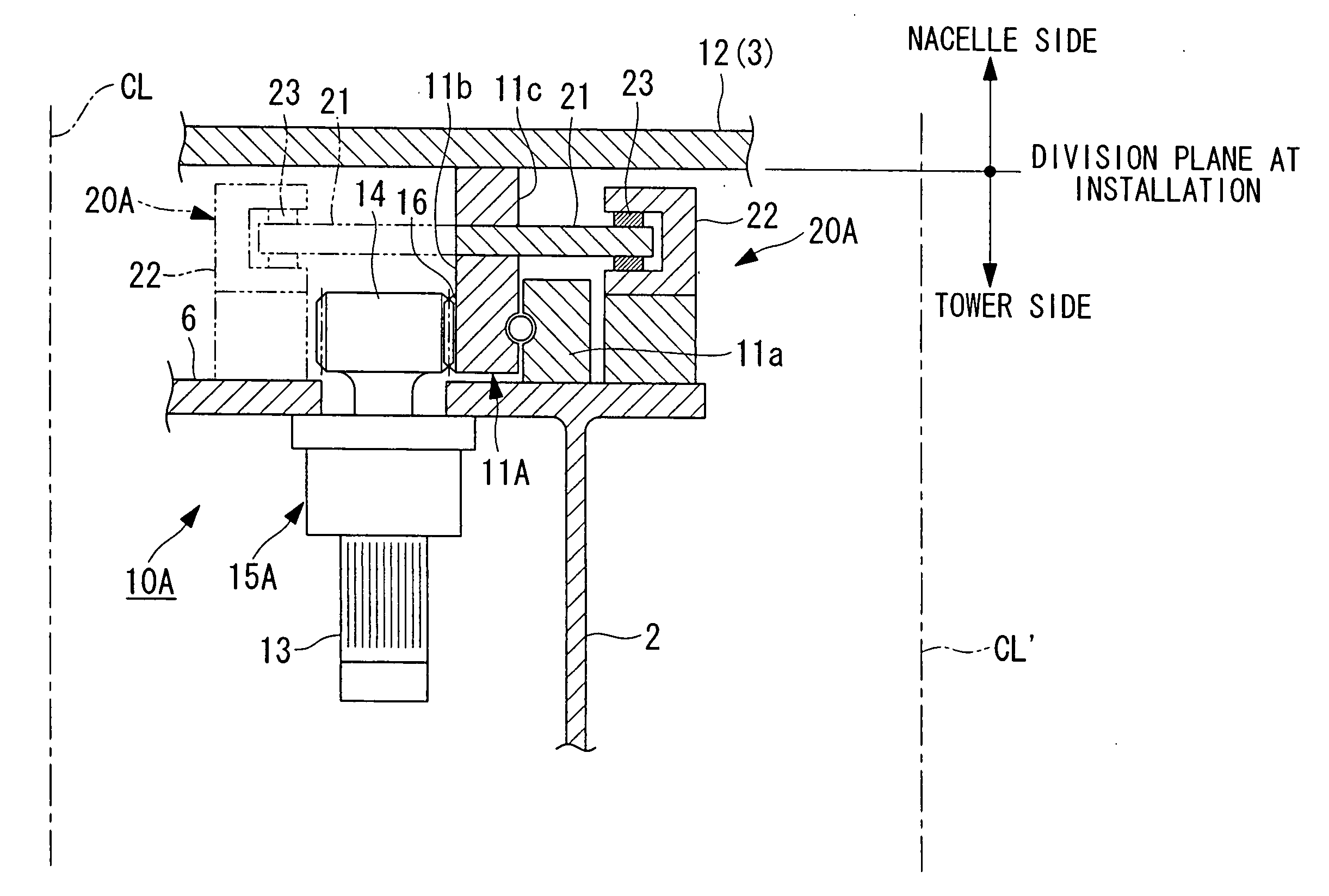
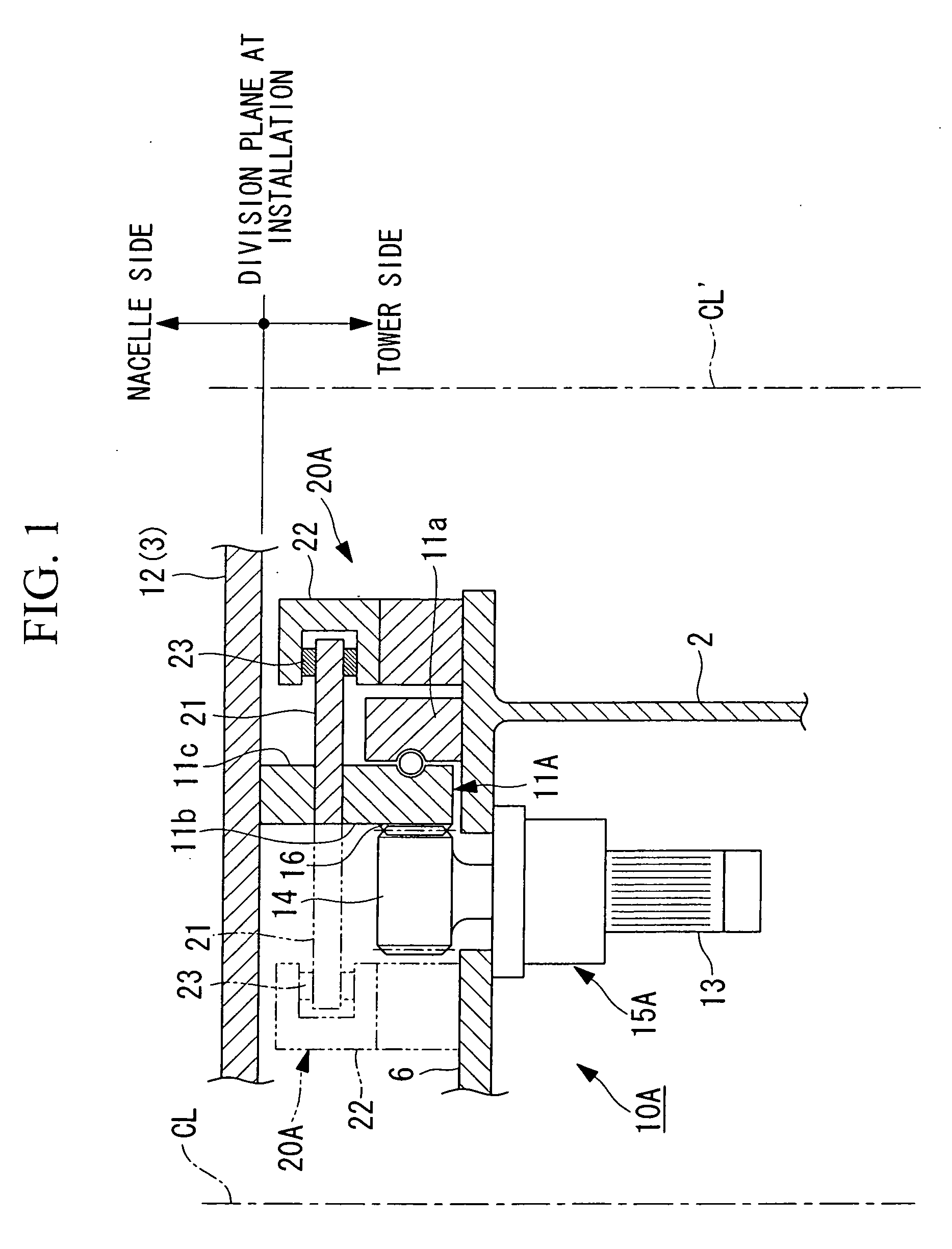
[0043]An embodiment of a wind turbine generator according to the present invention will now be described with reference to FIGS. 1 and 2.

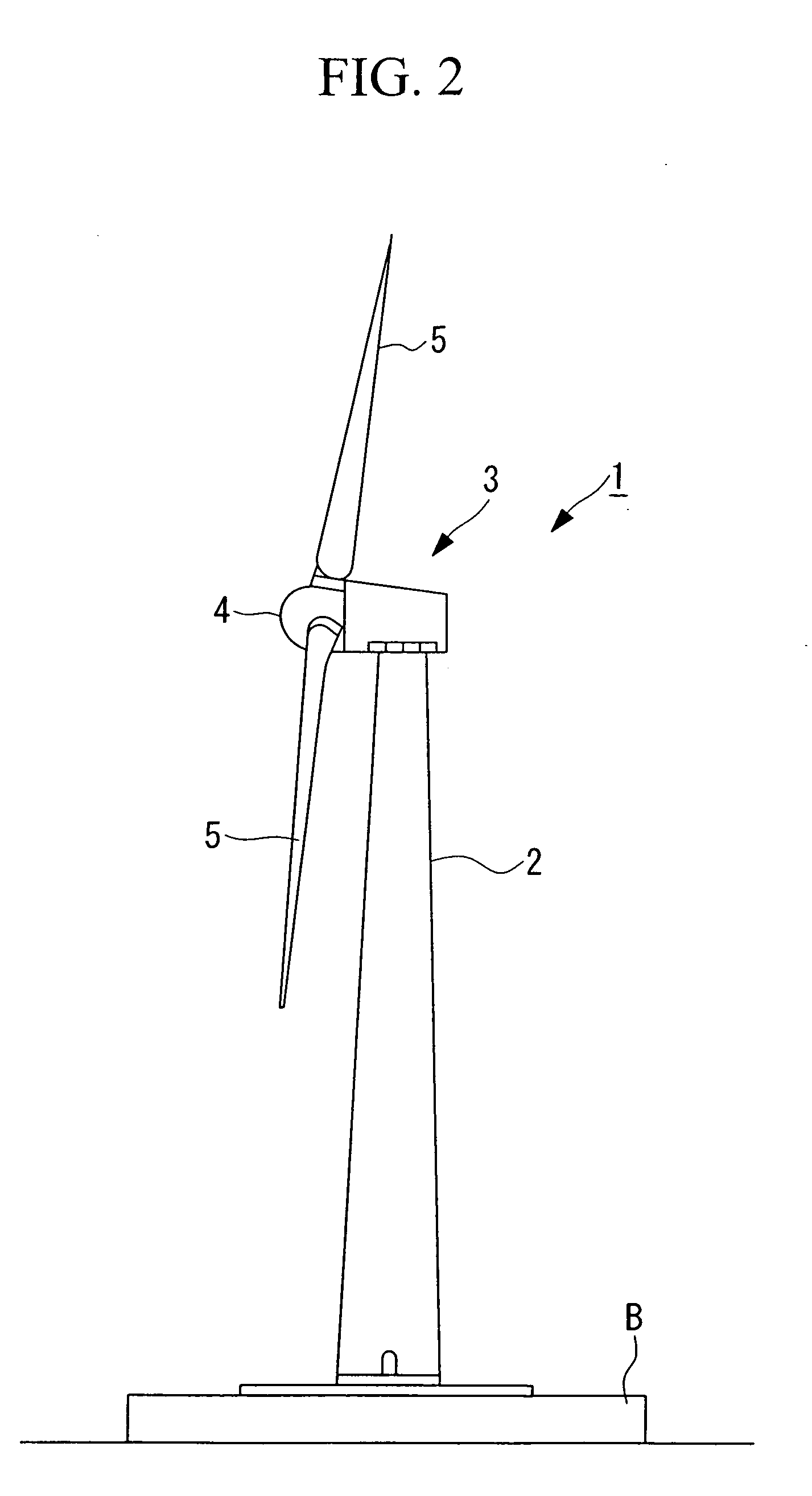
[0044]A wind turbine generator 1 shown in FIG. 2 includes a tower (also called “tower”) 2 disposed upright on a foundation B, a nacelle 3 mounted at the top end of the tower 2, and a rotor head 4 disposed on the nacelle 3 and supported so as to be rotatable about a substantially horizontal rotation axis.

[0045]The rotor head 4 has a plurality of (for example, three) wind turbine rotor blades 5 attached thereto radially around the rotation axis thereof. This allows wind power received by the wind turbine rotor blades 5 in the rotation-axis direction of the rotor head 4 to be converted into power rotating the rotor head 4 about the rotation axis.

[0046]The above wind turbine generator 1 includes a yaw system that slews the nacelle 3, which is positioned at the top end of the tower 2. This yaw system is a system for directing the nacelle 3 in the optimu...


PUM


Abstract

A wind turbine generator is provided that allows the use of a general-purpose crane for construction through a reduction in the weight of a nacelle. This wind turbine generator includes a yaw system that includes a yaw drive unit, a yaw slew ring, and a yaw brake and that slews the nacelle, mounted on top of a tower, depending on wind direction. This yaw system is disposed on the tower top side.

Description

TECHNICAL FIELD[0001]The present invention relates to a wind turbine generator including a yaw system that slews a nacelle (main body of a wind turbine) depending on wind direction and to a method for constructing the wind turbine generator.BACKGROUND ART[0002]Conventionally, a wind turbine generator that rotates a wind turbine by wind power and transmits the rotational movement to a generator to generate electricity includes a yaw system that slews a nacelle (turns its head) depending on wind direction.[0003]A conventional yaw system is constituted of a yaw drive unit, a yaw slew ring, and a yaw brake, and the main components are disposed on the nacelle side. That is, the operation of the yaw system allows the nacelle, on which a wind turbine and a power train that generates electricity by the rotational force thereof are mounted, to slew at the top of a tower so as to face the optimal direction depending on wind direction.[0004]For a yaw system 10 of a first conventional example s...

Claims


Application Information

Patent Timeline
IPC IPC(8): F03D9/00F03D11/04
CPCF03D7/0204F03D11/0008Y02E10/723Y02E10/721Y02E10/722F05B2260/90F03D80/70Y02E10/72F05B2230/50
Inventor NUMAJIRI, TOMOHIRO
Owner MITSUBISHI HEAVY IND LTD
Why Eureka
Try Eureka