Vehicular headlamp

a technology for vehicular headlamps and headlamps, which is applied in the field of projector-type vehicular headlamps, can solve the problems of vehicle headlamps, achieve the effects of reducing the area, reducing the length of the lamp in the front-back direction, and reducing the light reflection

Inactive Publication Date: 2011-01-20
KOITO MFG CO LTD
View PDF9 Cites 29 Cited by
  • Summary
  • Abstract
  • Description
  • Claims
  • Application Information

AI Technical Summary

Benefits of technology

[0013]In contrast, in the vehicular headlamp according to the related art, a liquid crystal shutter may be disposed only in an area that should be in the light shielding mode. With this configuration, it is possible to prevent the low-beam distribution pattern from being darkened.
[0040]In this case, the light source may be disposed below the optical axis, and the second reflector may be formed by a heat-ray transparent mirror. With this configuration, it is possible to effectively prevent the liquid crystal shutter from being heated by reflected light from the second reflector.

Problems solved by technology

However, the vehicular headlamps described in “Patent Document 2” and “Patent Document 3” suffer from the following problem.

Method used


Image

  • Vehicular headlamp
  • Vehicular headlamp
  • Vehicular headlamp

Examples


Embodiment Construction

[0047]Hereinafter, embodiments of the present invention will be described with reference to accompanying drawings.

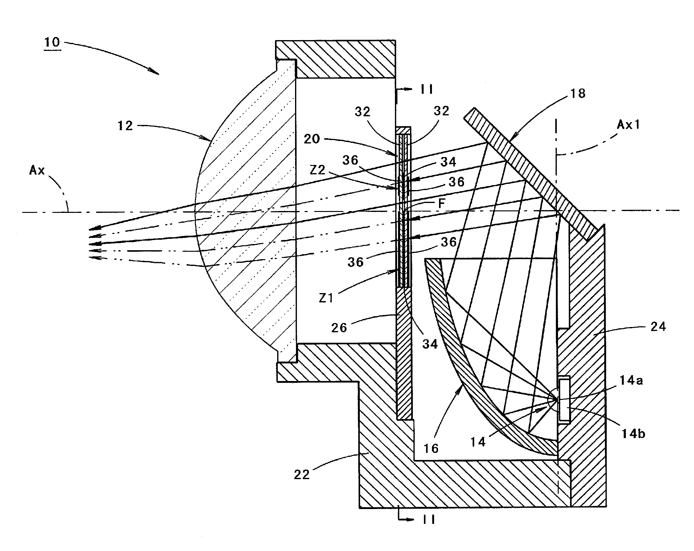
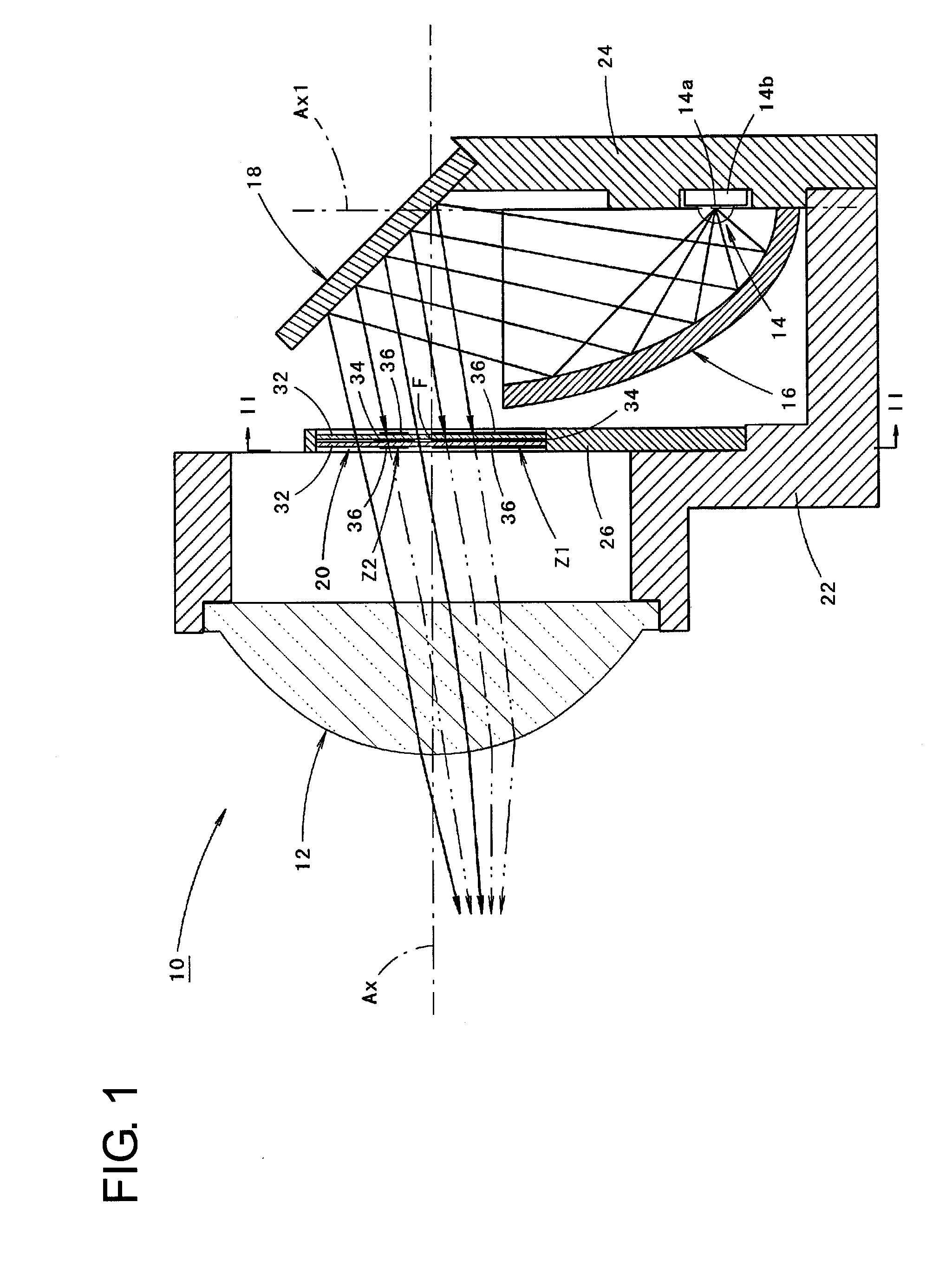
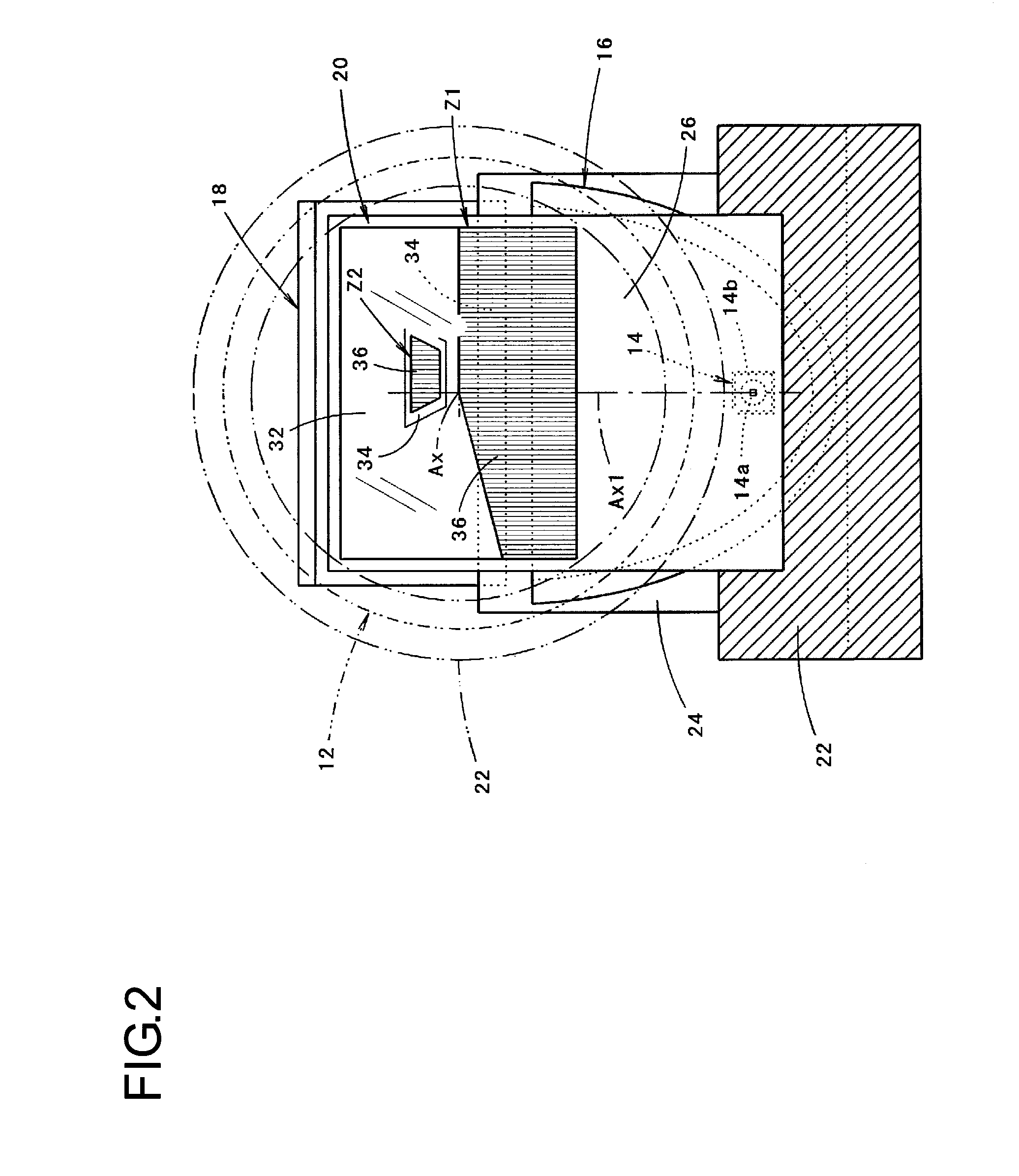
[0048]FIG. 1 is a side cross-sectional view showing a vehicular headlamp according to an embodiment of the present invention. FIG. 2 is a II-II cross-sectional view of FIG. 1.

[0049]As shown in the drawings, a vehicular headlamp 10 according to an embodiment is formed as a projector-type lamp unit, and is used as it is assembled in a lamp body (not shown) or the like as a part of a headlamp.

[0050]The vehicular headlamp 10 includes a projection lens 12 disposed on an optical axis Ax extending in a vehicular longitudinal direction, a light source 14a disposed rearwardly of a rear-side focal point F of the projection lens 12, first and second reflectors 16, 18 serving as a reflector disposed rearwardly of the rear-side focal point F to reflect light from the light source 14a toward the projection lens 12, a liquid crystal shutter 20 disposed in the proximity of the rear-side...


PUM


Abstract

A vehicular headlamp includes a projection lens, a light source, a reflector, and a liquid crystal shutter. The liquid crystal shutter includes a pair of transparent plates, a liquid crystal member, and a pair of polarization plates. The liquid crystal member is disposed only in a part of an area between the pair of transparent plates. The pair of polarization plates are disposed only in an area of the outer surface of the pair of transparent plates corresponding to an area in which the liquid crystal member is disposed. The area in which the liquid crystal member is disposed includes a first area for blocking a part of reflected light from the reflector such that light emitted from the projection lens forms a low-beam distribution pattern having a cut-off line at an upper end edge, and a second area for blocking light emitted from the projection lens and then reflected by a road surface ahead of a vehicle toward a space above the cut-off line.

Description

BACKGROUND OF INVENTION[0001]1. Field of the Invention[0002]The present invention relates to a so-called projector-type vehicular headlamp, and, in particular, to a vehicular headlamp including a liquid crystal shutter.[0003]2. Related Art[0004]In projector-type vehicular headlamps, in general, a projection lens is disposed on an optical axis extending in a vehicular longitudinal direction, a light source is disposed rearwardly of a rear-side focal point of the projection lens, and a reflector reflects light from the light source toward the projection lens. In order for a projector-type vehicular headlamp to form a low-beam distribution pattern, a shade that blocks a part of reflected light from the reflector is disposed in the proximity of the rear-side focal point of the projection lens with the upper end edge of the shade positioned in the proximity of the optical axis, so as to form a cut-off line at the upper end edge of the low-beam distribution pattern.[0005]“Patent Document ...

Claims


Application Information

Patent Timeline
Patent Type & Authority Applications(United States)
IPC IPC(8): B60Q1/04
CPCF21S48/1731F21S48/114B60Q1/085B60Q2300/056B60Q2300/312B60Q2300/32F21S41/135F21S41/645
Inventor KOBAYASHI, SHOJI
Owner KOITO MFG CO LTD
Why Eureka
Try Eureka