
Eureka
For R&D, Eureka makes reading and utilizing patents & technical documents easy.
Eureka AIR
Designed for self-driven R&D workflows. Generate viable solutions, solve complex R&D challenges, empower your innovation with AI.

Eureka Materials
Designed for material experts only. Revolutionize your material R&D, from search, analyze, to developing new materials.

TechResearch
Generate reliable direction feasibility study reports for your R&D in just a few steps.

TechSeek
Discover and master advanced knowledge NOW. Basics, ideas, possibilities, all at once.

TechMind
As an expert in R&D Theories, TechMind can generates customized viable solutions instantly.

TechRisk
Analyze your overall solution with one click, know your potential R&D risks in advance.

TechMonitor
Get weekly tech updates, stay abreast of the latest tech innovations and key insights.
Seals for a turbine engine, and methods of assembling a turbine engine
- Summary
- Abstract
- Description
- Claims
- Application Information
AI Technical Summary
Problems solved by technology
Method used
Image

Examples
Embodiment Construction
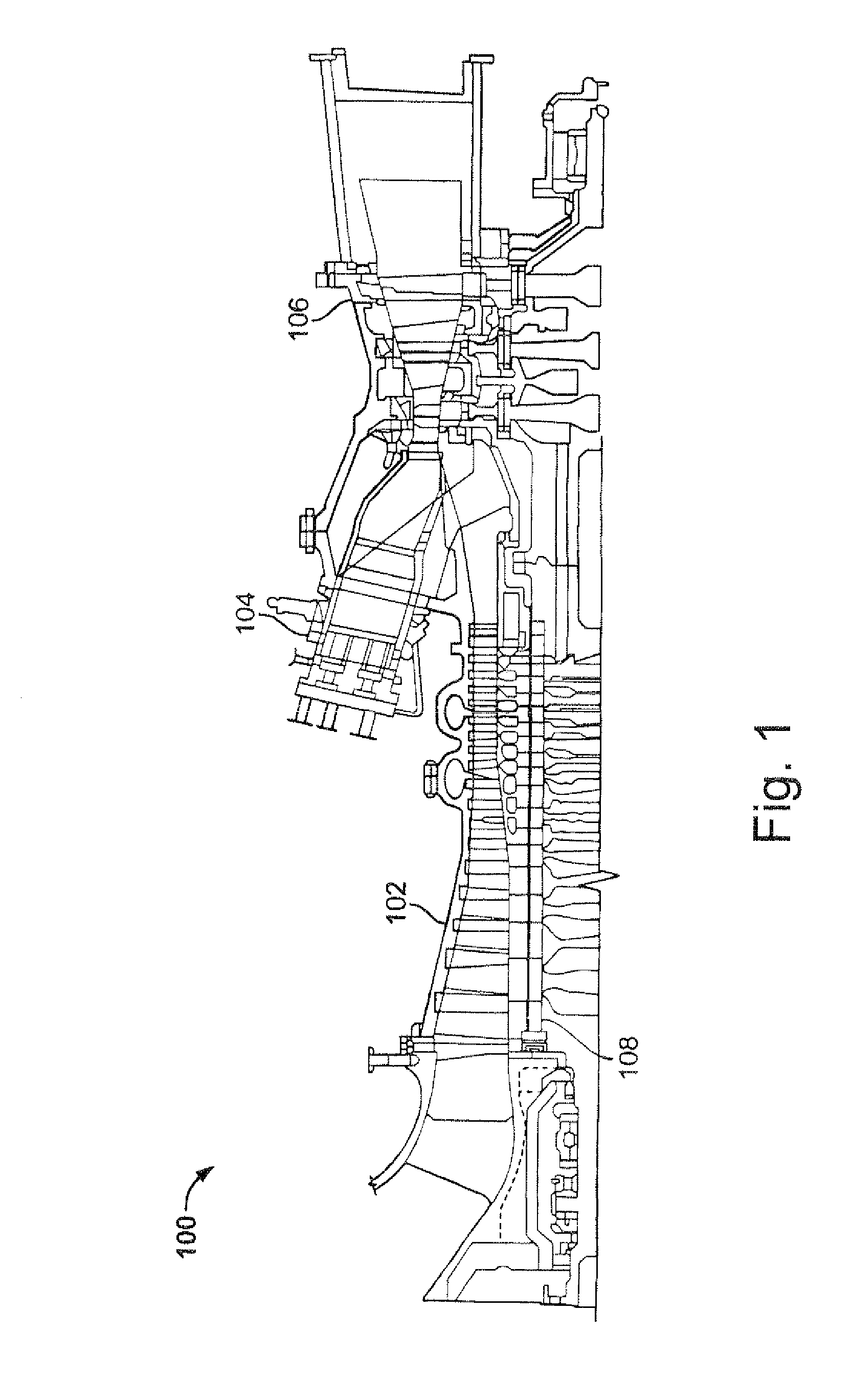
[0018]FIG. 1 illustrates some of the major elements of a typical turbine engine which would be used in a power generating facility. The turbine engine 100 includes a compressor section 102 which compresses incoming air and delivers it to a combustor 104. The compressed air is mixed with fuel in the combustor 104 and the air fuel mixture is ignited. The resulting hot combustion gases are then sent through an outlet of the combustor 104 into an inlet annulus of the turbine section 106.
[0019]As mentioned above, a plurality of combustors 104 would be arranged around the exterior circumference of the turbine engine 100. The outlets of each of the combustors 104 would be attached to an inlet annulus which opens into the turbine section 106 of the engine 100.
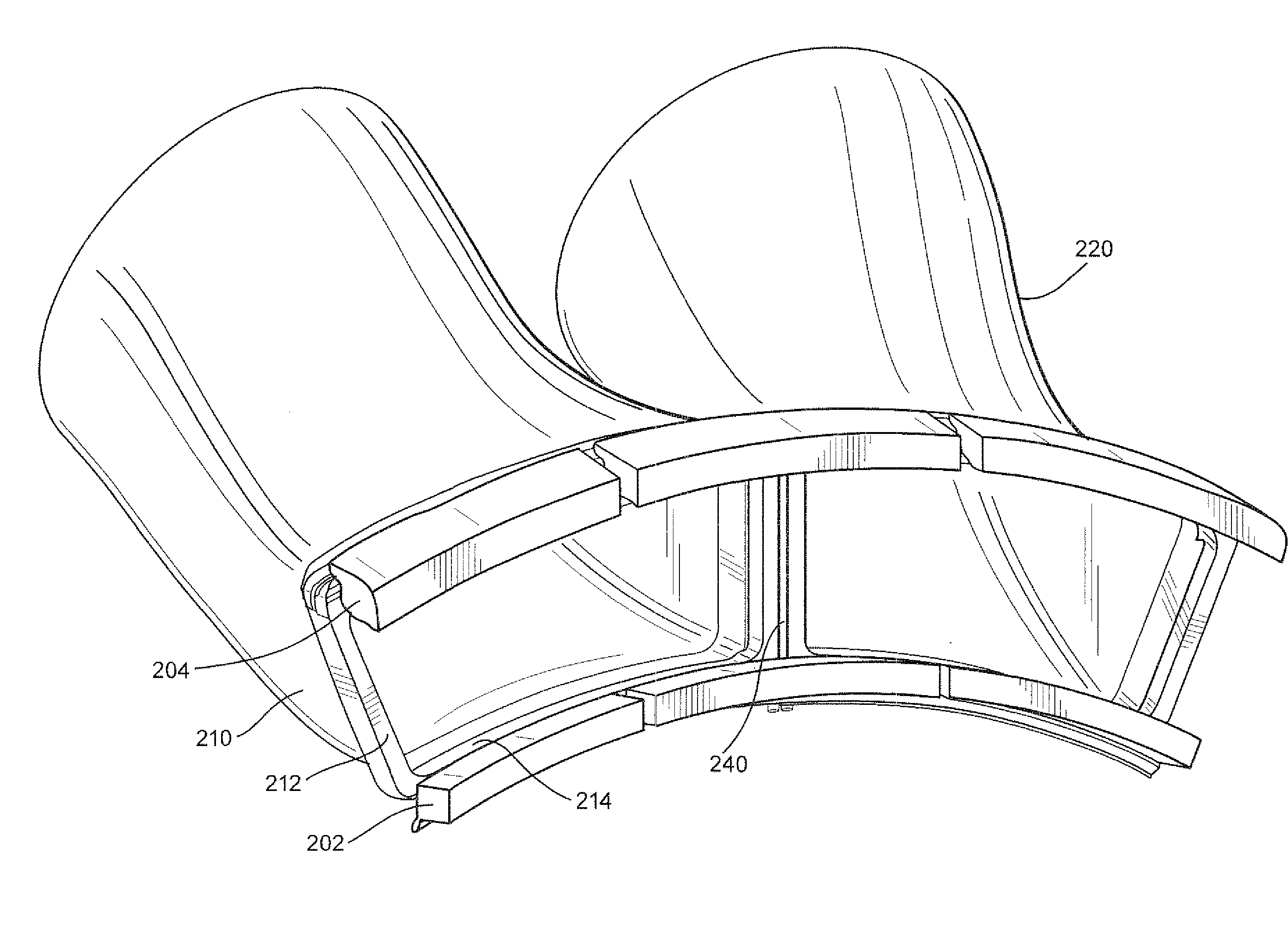
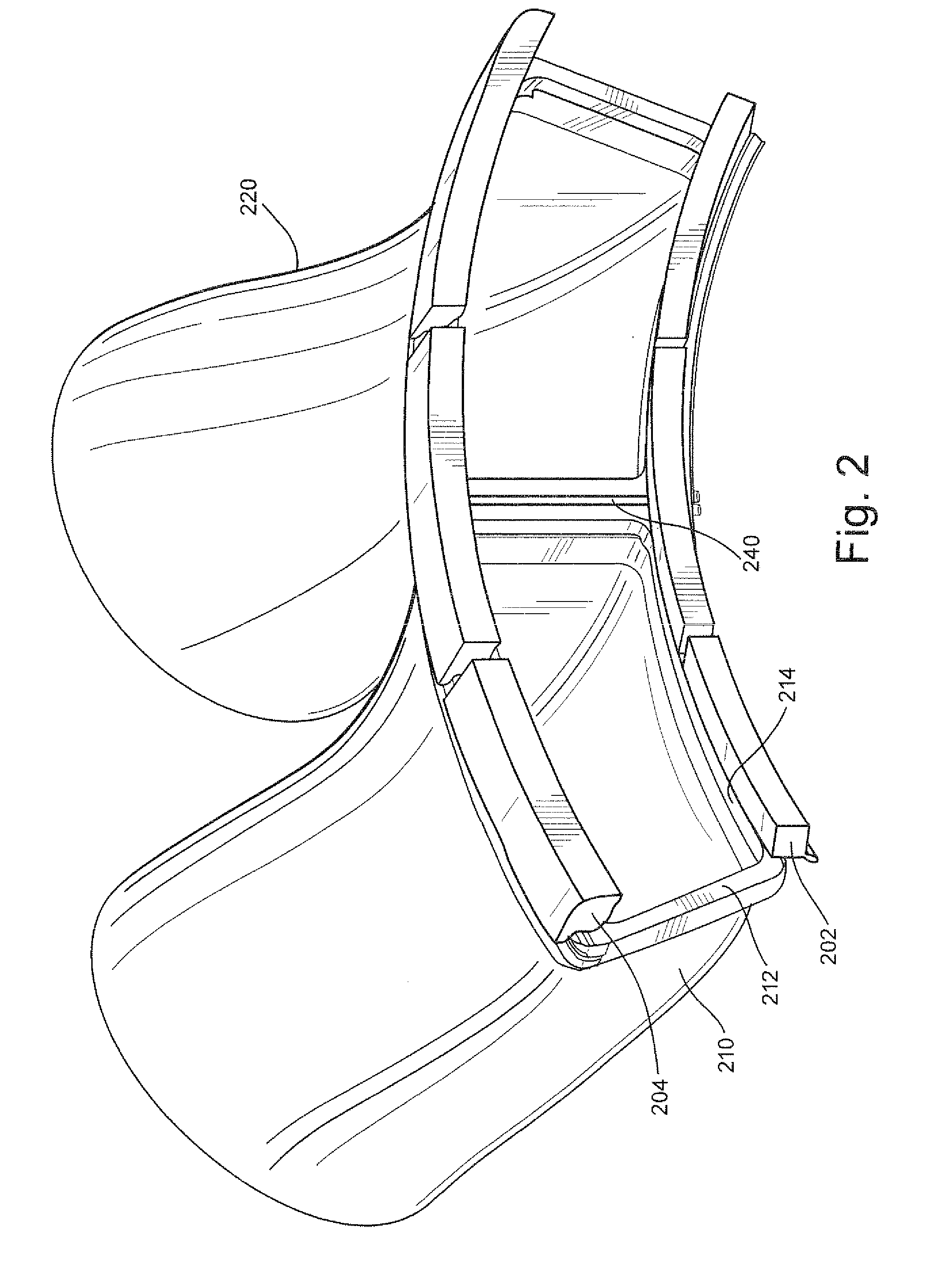
[0020]FIG. 2 illustrates how two adjacent combustor outlets are joined to the inlet annulus which opens into the turbine section 106 of the engine 100. The inlet annulus is formed by the inner annulus wall 202 and the outer annulus wal...
PUM
 Abstract
Description
Claims
Application Information
 - R&D Engineer
- R&D Manager
- IP Professional
- Industry Leading Data Capabilities
- Powerful AI technology
- Patent DNA Extraction
Browse by: Latest US Patents, China's latest patents, Technical Efficacy Thesaurus, Application Domain, Technology Topic, Popular Technical Reports.
© 2024 PatSnap. All rights reserved.Legal|Privacy policy|Modern Slavery Act Transparency Statement|Sitemap|About US| Contact US: help@patsnap.com