System for automatically landing aircraft using image signals and method of controlling the same

a technology of image signals and aircraft, applied in the direction of image enhancement, landing aids, instruments, etc., can solve the problems of high cost equipment installation on the ground, easy disturbance of radar waved, and maintenance of additional manpower

Active Publication Date: 2011-01-20
KOREA AEROSPACE RES INST
View PDF3 Cites 10 Cited by
  • Summary
  • Abstract
  • Description
  • Claims
  • Application Information

AI Technical Summary

Problems solved by technology

However, the landing methods require the maintenance of additional manpower and the provision of additional facilities.
However, the system for automatically landing an aircraft having the above-described construction has a defect in that high cost equipment needs to be installed on the ground so as to radiate the radar waves.
Furthermore, there is a problem in that radar waved are easily exposed to disturbances which interrupt the radio waves.

Method used


Image

  • System for automatically landing aircraft using image signals and method of controlling the same
  • System for automatically landing aircraft using image signals and method of controlling the same
  • System for automatically landing aircraft using image signals and method of controlling the same

Examples


Embodiment Construction

[0032]Reference now should be made to the drawings, in which the same reference numerals are used throughout the different drawings to designate the same or similar components.

[0033]Preferred embodiments of the present invention will be described in detail below with reference to the accompanying drawings. Prior to the description, it should be noted that the terms and words used in the present specification and the attached claims should not be interpreted as having common meanings or meanings in a dictionary but should be interpreted as having meanings suitable for the technical spirit of the present invention on the basis of the principle in which an inventor can appropriately define the concepts of terms in order to describe his or her invention in the best way.

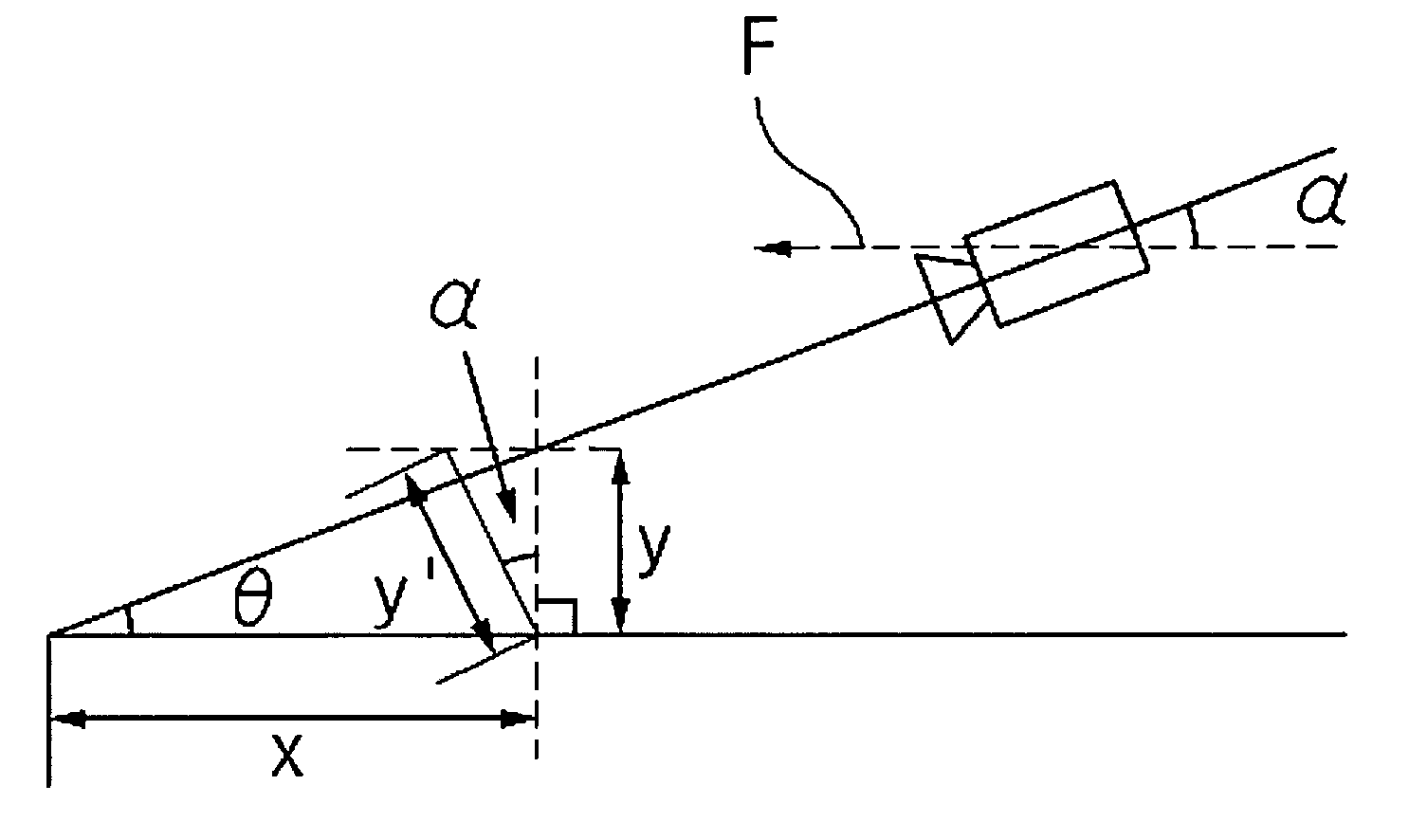
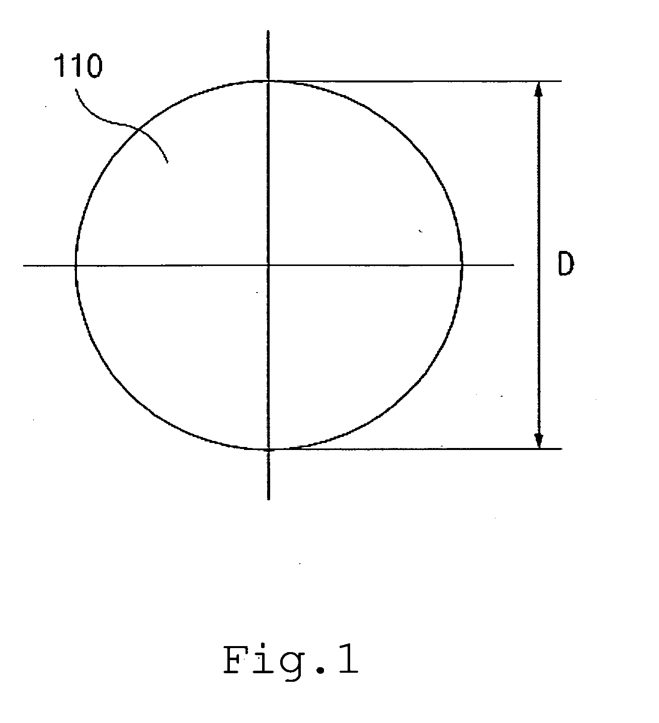
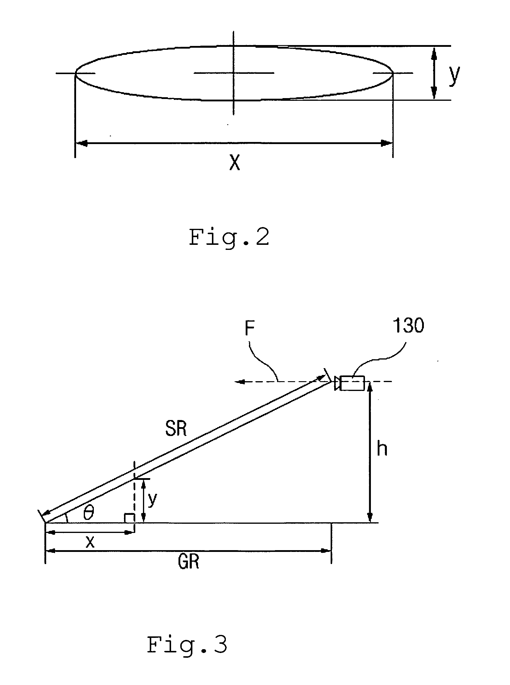
[0034]FIG. 1 is a plan view showing a landing mark for a system for automatically landing an aircraft using image signals according to the present invention, and FIG. 2 is a plan view showing the shape of the landing mark...


PUM


Abstract

Disclosed herein are a system for automatically landing an aircraft using image signals and a method of controlling the system. The system includes an altimeter installed on the aircraft; a landing mark placed at a landing location on a landing runway; a camera installed on the aircraft, oriented toward the front of the aircraft, and configured to detect the shape of the landing mark in image information form; and a FCC configured to calculate the angle between the aircraft and the ground, the ground range and the slant range between the aircraft and the landing location using the altitude information measured by the altimeter, the image information of the landing mark captured by the camera, angle information composed of the pitch, roll and yaw angles of the aircraft, and the angle of entry into the landing runway, and configured to control the automatic landing of the aircraft.

Description

[0001]This is a Divisional of U.S. application Ser. No. 12 / 363,185, filed Jan. 30, 2009, the subject matter of which is incorporated herein by reference.BACKGROUND OF THE INVENTION[0002]1. Field of the Invention[0003]The present invention relates generally to a system for automatically landing an aircraft using image signals, and, more particularly, to a system for automatically landing an aircraft using image signals and a method of controlling the system, which are capable of automatically landing an aircraft at a landing location using a landing mark provided at the landing location and imaging equipment configured to detect the landing mark.[0004]2. Description of the Related Art[0005]In order to land an aircraft, particularly an unmanned aircraft, a landing method based on an external pilot's control, a landing method using a parachute or a net and an automatic landing method using an Instrument Landing. System (ILS) have been used.[0006]However, the landing methods require the...

Claims


Application Information

Patent Timeline
Patent Type & Authority Applications(United States)
IPC IPC(8): G05D1/06G06V10/32
CPCG05D1/0676G06K9/42G06T7/0042G06T2207/30252G06T2207/10048G06T2207/30244G06T2207/10016G06T7/73G06V10/32B64F1/18B64F1/20
Inventor LEE, HYEON-CHEOL
Owner KOREA AEROSPACE RES INST
Why Eureka
Try Eureka