Compressed gas cartridge lance housing

a gas cartridge and lance technology, applied in the direction of manufacturing tools, container discharging methods, soldering devices, etc., can solve the problems of difficult or impossible molding of the feature of the mold, and achieve the effect of reducing material and labor expenses, reducing manufacturing tolerances of components, and sacrificing quality

Active Publication Date: 2011-01-27
ILLINOIS TOOL WORKS INC
View PDF8 Cites 33 Cited by
  • Summary
  • Abstract
  • Description
  • Claims
  • Application Information

AI Technical Summary

Benefits of technology

[0017]Accordingly, several objects and advantages of the present invention will be presented in the following paragraphs followed by a thorough disclosure of each aspect in the accompanying embodiments in the DETAILED DESCRIPTION.
[0018]In light of the above-mentioned problems, it is therefore an object of the present invention to provide a quick method of manufacturing a compressed gas dispenser therefore reducing material and labor expenses.
[0019]Further, it is another object of the present inven

Problems solved by technology

One obvious advantage to this method of manufacturing a compressed gas cartridge seal pocket by the i

Method used


Image

  • Compressed gas cartridge lance housing
  • Compressed gas cartridge lance housing
  • Compressed gas cartridge lance housing

Examples


Embodiment Construction

[0048]The following paragraphs will detail, at minimum, the best mode of the present invention. The exemplary figures and description of the invention as it is exemplified in each figure is representative of the current invention and the scope of the invention disclosure is not intended to be limited by the exemplary teachings. Like physical structure in different figures share the same identifying numbers.

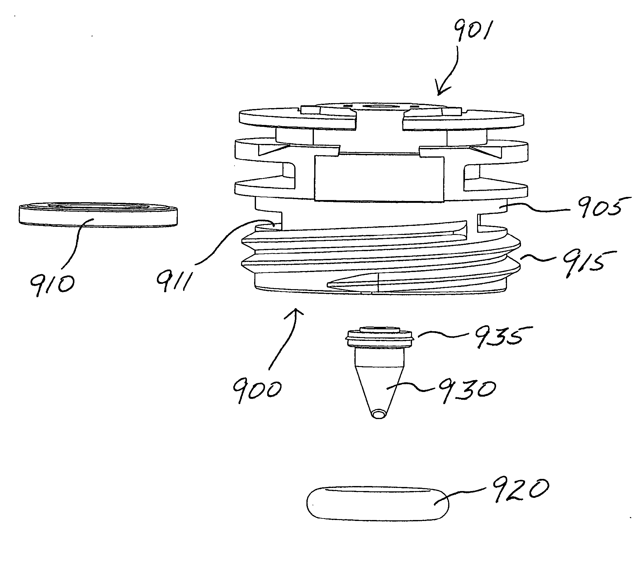
[0049]FIG. 9 illustrates a side view of an exemplary lance housing assembly in a compressed gas cartridge dispensing head, in accordance with an embodiment of the present invention. An inlet end 900 and an outlet end 901 of a compressed gas cartridge dispensing head 905 are shown. Inlet end 900 is the end of the dispensing head that contains the compressed gas cartridge lancing means. Outlet end 901 is illustrated as truncated downstream from the compressed gas cartridge lancing means. The aforementioned prior-art examples offer some suggestion as to the type of apparatus that out...


PUM


Abstract

The present invention minimizes the assembly time of a dispenser head by inserting a rigid seal retaining element. The seal retaining element comes in different configurations thus allowing a variety of compressed gas cartridge dispensing options. Additional features are integrated into a molded dispenser head thus requiring fewer components to accomplish a useable dispenser thus reducing manufacturing costs. Reliance on conformable plastic allows for relaxed dimensional tolerances. This method of making a dispenser head can equally apply to threaded or non-threaded lance housings.

Description

CROSS REFERENCE TO RELATED APPLICATIONS[0001]This application is a Continuation Application claiming priority from a United States Utility Application having Ser. No. 11 / 195,090 filed Aug. 1, 2005.FEDERALLY SPONSORED RESEARCH[0002]Not applicable.REFERENCE TO A MICROFICHE APPENDIX[0003]Not applicable.FIELD OF INVENTION[0004]The present invention relates to the field of portable pneumatic dispensers capable of being manufactured at a reduced cost and allowing fast assembly.BACKGROUND OF THE INVENTION[0005]Many current art compressed gas dispensers, particularly the models manufactured by Genuine Innvations, Inc, in Tucson, Ariz. U.S.A. are manufactured to dispense a non-threaded neck compressed gas cartridge, a threaded neck compressed gas cartridge or capable of dispensing both cartridge species within the same dispense.[0006]One feature of current art compressed gas dispensers is a lance housing that has been used in part to contain the high pressure from a compressed gas cartridge....

Claims


Application Information

Patent Timeline
IPC IPC(8): B23P11/00
CPCF16J15/0825F16J15/0831F17C13/06F17C2201/058F17C2205/032Y10T29/49414Y10T29/49412Y10T29/49826Y10T29/49405Y10T29/49417F17C2260/013Y10T137/6123Y10T137/86686Y10T137/86895
Inventor HOLLARS, ANTHONY S.
Owner ILLINOIS TOOL WORKS INC
Why Eureka
Try Eureka