Counterbalance mechanism for end-effector configuration and method of use

a technology of end-effector and configuration, applied in the direction of mechanical control devices, process and machine control, instruments, etc., can solve the problems of clutch to chatter or bind, typical concept of gravity counterbalance never perfectly balanced, and the effect of re-balancing continues to occur

Active Publication Date: 2011-01-27
GM GLOBAL TECH OPERATIONS LLC
View PDF8 Cites 13 Cited by
  • Summary
  • Abstract
  • Description
  • Claims
  • Application Information

AI Technical Summary

Benefits of technology

[0006]A counterbalance mechanism to be used during the set-up and adjustment of a reconfigurable end-effector with an articulating frame that is rotated by a bi-directional rotary locking mechanism, or clutch, is provided. The counterbalance mechanism provides an opposing load to counteract the gravity moment load of the articulating portion of the end-effector frame as the articulating portion is rotated in the same direction as the input shaft of the clutch. Unless counterbalanced, the gravity moment load of the rotating end-effector frame may accelerate the rotation of the output shaft faster than the input shaft of the clutch, causing the clutch to “overhaul.” This overhauling effect may include clutch chattering or binding stops.
[0007]The counterbalance mechanism of the present invention is attached to a set-up stand and to the articulating portion of the end-effector frame, and is actuated during rotation of the end-effector frame to provide a tension load counterbalancing the gravity moment load of the articulating end-effector frame as it is rotated either clockwise or counter clockwise to a reconfigured position. Counterbalancing the gravity moment load of the articulating portion of the end-effector frame during rotation reduces the torque load on the output shaft, and therefore reduces the potential for the output shaft to accelerate faster than the input shaft of the clutch, thereby minimizing clutch overhauling and preventing chattering or binding stops during the reconfiguration event.
[0008]Further, the present invention provides an advantage over typical counterbalance springs where variability in free length of a fixed end spring is detrimental to establishing a perfect counterbalance. In the present invention, a counterbalance mechanism is configured to position the spring out of the direct tension load path, and to preload the counterbalance to eliminate variability in free length of a fixed end spring of the counterbalance mechanism. Additional advantages of the present invention include the weight reduction and clearance advantages resultant from providing a counterbalance mechanism located on a set-up stand, and not on the end-effector.
[0011]By rotating the input shaft, a bi-directional locking rotary device, such as a clutch, is released so that the articulating portion of the end-effector can be rotated by a rotational or output shaft, from a first position to a second position. The holding member moves from an initial position to a final position and remains continuously connected to the articulating portion during rotation of the articulating portion from a flat frame to an articulated position. The counterbalance load provided by the counterbalance mechanism is sufficient to offset the gravity moment load and prevent the rotational or clutch output shaft from rotating faster than the clutch input shaft, therefore minimizing any overhauling effect and preventing chattering or binding stops of the clutch during the reconfiguration event.

Problems solved by technology

However, unlocking the bi-directional clutch with the input shaft and output shaft rotating in the same direction creates the potential for an “overhauling effect” where the output shaft accelerates faster than the input shaft, causing the clutch to chatter or bind.
However, this typical concept of a gravity counterbalance is never perfectly balanced due to variability in the free length of the extension spring.
If the spring stiffness is inadequate, the overhauling effect will continue to occur.
If the spring is too stiff, the counterbalance will exert unnecessary resistance to the articulation effort.

Method used


Image

  • Counterbalance mechanism for end-effector configuration and method of use
  • Counterbalance mechanism for end-effector configuration and method of use
  • Counterbalance mechanism for end-effector configuration and method of use

Examples


Embodiment Construction

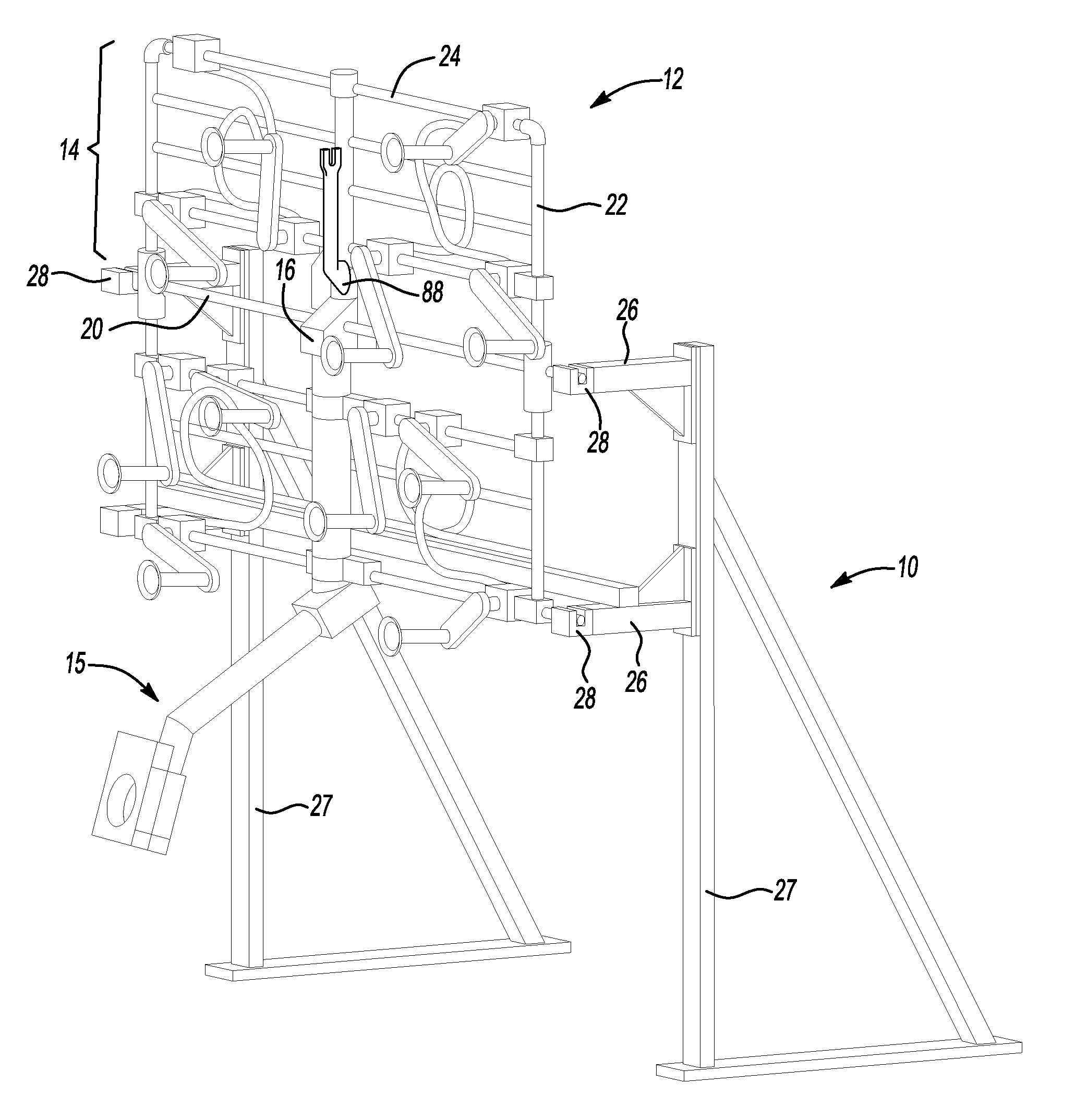
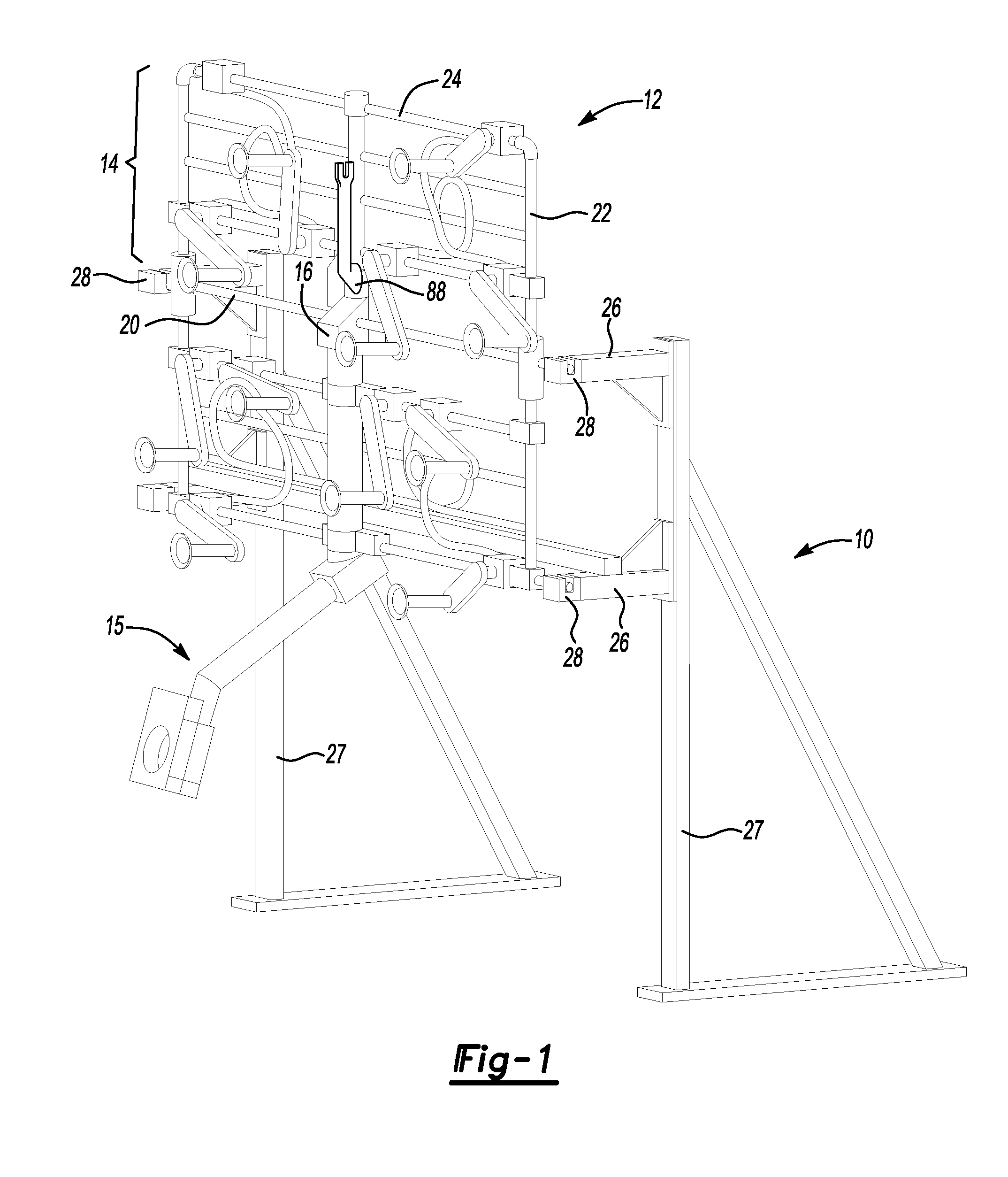
[0019]Referring to the drawings wherein like reference numbers represent like components throughout the several figures, and beginning with FIG. 1, a stand, also referred to as a set-up stand, set-up fixture or fixturing stand, is generally indicated at 10. The stand 10 includes a leg 27 which is generally vertical with respect to the stand base, and may include other members configured to make stand 10 a freestanding unit or provide the structural strength and configuration required to support an end-effector such as the end-effector generally indicated at 12. Stand 10 may be connected by a transverse member of other means to another stand of same or different configuration to function as a set-up stand assembly or fixture assembly. Stand 10 includes one or more arms 26 shown in FIG. 1 attached to leg 27 in a generally horizontal orientation to provide a support surface upon which end-effector 12 can be located. One or more arms 26 may be oriented other than horizontally, as requir...


PUM


Abstract

A set-up stand is provided including a counterbalance mechanism for use in reconfiguring an end-effector with an articulating portion rotated by a bi-directional rotary locking device, for example, a clutch. A counterbalance mechanism is provided including a holding member which is attached to a preloaded member and connected to an articulating portion of the end-effector during reconfiguration of the end-effector. The preloaded member provides a tension load to counterbalance the gravity moment load of the articulating portion when the articulated portion is rotated in the same direction as the output shaft of the bi-direction rotary locking device, to prevent overhauling, chattering or binding stops during rotation and reconfiguration. A method is provided to utilize the counterbalance mechanism as described.

Description

CROSS-REFERENCE TO RELATED APPLICATIONS[0001]This application claims the benefit of U.S. Provisional Patent Application No. 61 / 228,408 filed Jul. 24, 2009, and which is hereby incorporated by reference in its entirety.TECHNICAL FIELD[0002]This invention relates to a mechanism to counterbalance the gravity moment load of the articulating portion of a reconfigurable end-effector during set-up and adjustment.BACKGROUND OF THE INVENTION[0003]An end effector is a device connected to the end of a robot arm that interacts with the environment, for example, with an automotive body panel or windshield in an automotive assembly environment, to perform a task. The structure of an end effector and tooling or fixturing included as part of the end effector depends on the task the robot will be performing. The end-effector may include vacuum cup tool modules which are pneumatically actuated. The end effector may have articulating portions, such as an articulating frame, that allow the end-effector...

Claims


Application Information

Patent Timeline
Patent Type & Authority Applications(United States)
IPC IPC(8): B25J18/00F16M13/00
CPCB25J15/0491Y10T74/20305B25J15/0061B25J9/104B25J15/0052B25J19/0008B25J19/0016B25J19/002F16M11/2021F16M2200/044F16M2200/063
Inventor LIN, YHU-TINBARTOS, ANDREW L.
Owner GM GLOBAL TECH OPERATIONS LLC
Why Eureka
Try Eureka