
Compressed Elastomer Process for Autofrettage and Lining Tubes

a technology of elastomer and compression elastomer, which is applied in the direction of furnaces, heat treatment equipment, heat treatment furnaces, etc., can solve the problems of high-pressure fluid rapid and/or uncontrolled release, requiring additional safety equipment, and requiring dangerous releas

Inactive Publication Date: 2011-01-27
US SEC THE ARMY THE
View PDF15 Cites 2 Cited by
  • Summary
  • Abstract
  • Description
  • Claims
  • Application Information

AI Technical Summary

Problems solved by technology

In. addition, the use of hydraulic autofrettage requires the use of high-pressure seals to be attached to the tube, gun barrel, etc., and with equipment failure can result in the rapid and / or uncontrolled release of high-pressure fluid.
Such a release is dangerous and requires additional safety equipment to be used with hydraulic autofrettage systems.

Method used

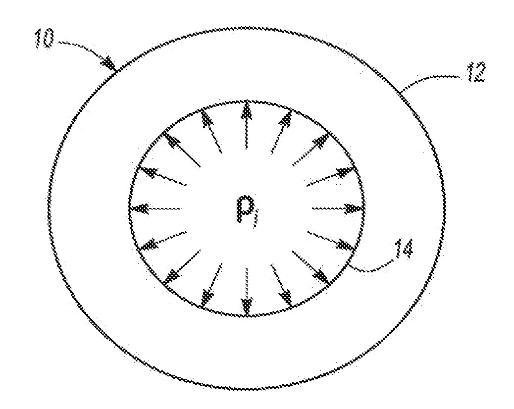
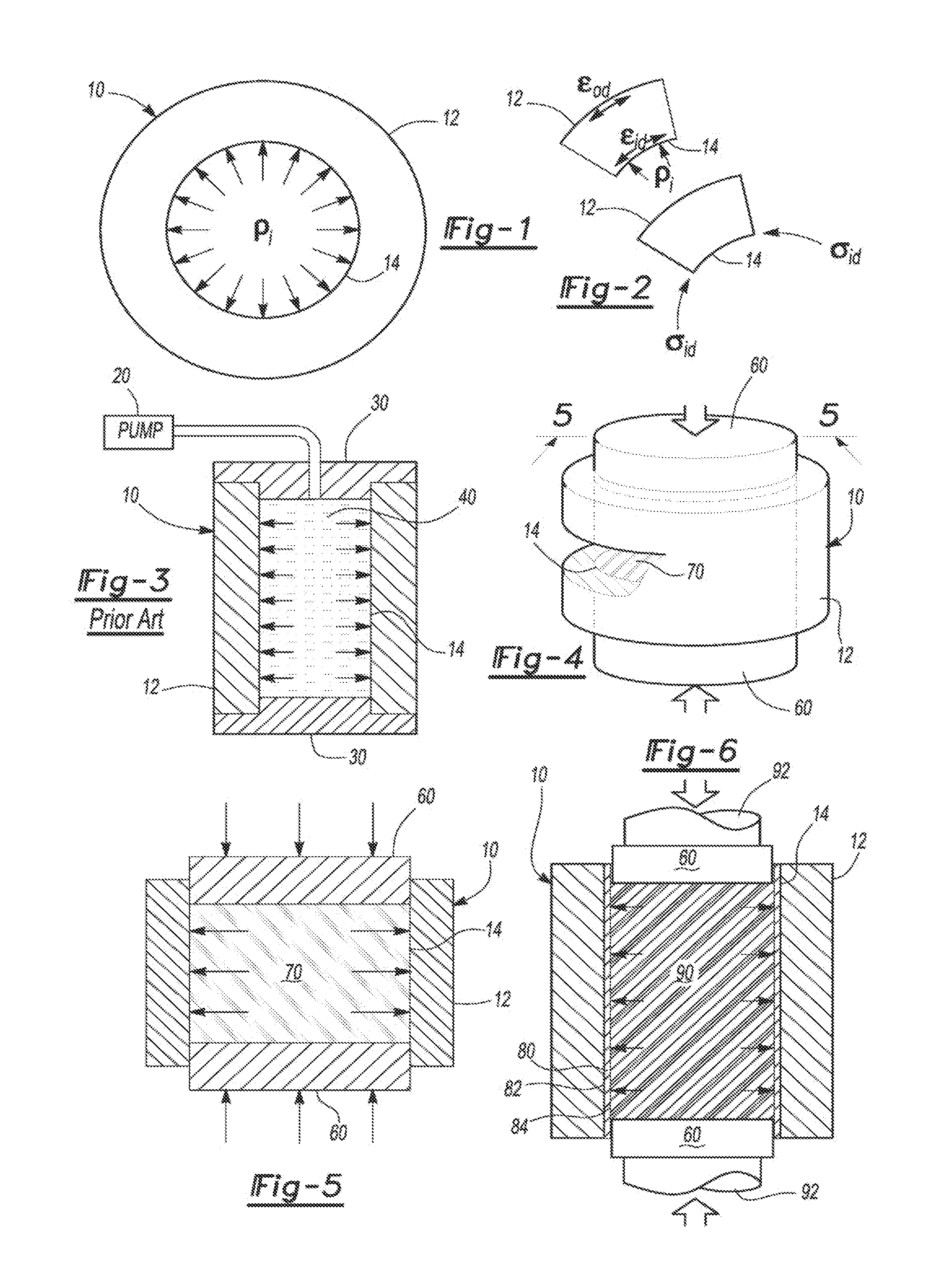

Image

  • Compressed Elastomer Process for Autofrettage and Lining Tubes
  • Compressed Elastomer Process for Autofrettage and Lining Tubes

Examples


Embodiment Construction

[0016]The present invention discloses an inventive process for autofrettaging structures. As such, the process has utility for providing such structures with increased fatigue resistance.

[0017]The inventive process includes providing a structure that has an outer surface and an inner surface. An expander is placed adjacent to the inner surface of the structure and an axial compressive force is applied thereto. Preferably, the expander is made from an elastomer or a plastic having a Poisson's ratio between 0.3 and 0.5 inclusive and, more preferably, an elastomer or a plastic having a Poisson's ratio between 0.4 and 0.5 inclusive. The expander can be a solid form such as a plug, a particulate such as granules or shredded material, or a combination of both.

[0018]With the compressive force applied along the axial direction of the expander, it expands in a radial direction and thereby provides a pressure to the inner surface of the structure. It is appreciated that the structure can be a...


PUM

PropertyMeasurementUnit
Poisson's ratioaaaaaaaaaa

Abstract

An inventive process is provided for creating residual compressive stress at a surface of a structure without resort to custom mandrels and dangerous high-pressure fluids. The inventive process yields autofrettage of a structure such as a tube, gun barrel and the like, the structure having an outer surface and an inner surface.

Description

GOVERNMENT INTEREST[0001]The invention described herein may be manufactured, used, and licensed by or for the United States Government.FIELD OF THE INVENTION[0002]The present invention relates in general to a process for autofrettaging a structure, and in particular, to a process for autofrettaging a structure, for example as a gun barrel, using an expander.BACKGROUND OF THE INVENTION[0003]It is well known that a residual compressive stress at a component surface can increase the strength and fatigue life of the component. For example, residual compressive stresses imposed on inner surfaces of tubes can provide resistance to fatigue and inhibit crack initiation and the rate of crack propagation. Such results are possible since the propagation of a crack requires tensile stresses to be present at the tip of the crack, and if a surface is under compression, the compressive stress must be overcome—in addition to any tensile stresses required for crack initiation and / or crack propagatio...

Claims


Application Information

Patent Timeline
Patent Type & Authority Applications(United States)
IPC IPC(8): F41A21/00F41A21/04
CPCB23P9/00C21D7/12C21D9/08Y10T29/49863C21D9/12Y10T29/49869C21D9/10
Inventor CARTER, ROBERT HANSBROUGHDEROSSET, WILLIAM STEINLE
Owner US SEC THE ARMY THE
Learn More