RFID tag

Active Publication Date: 2011-01-27
CONFIDEX OY
View PDF1 Cites 20 Cited by
  • Summary
  • Abstract
  • Description
  • Claims
  • Application Information

AI Technical Summary

Benefits of technology

[0005]The high temperature RFID tag according to the present solution provides several advantages. The structure of the tag is flexible since the tag is manufactured in the reel-to-reel format (as a label type product)

Problems solved by technology

There are a few factors which have an effect on the proper functioning of the tag in high temperature conditions and in conditions where there are, in addition to the high temperature also other disadvantageous conditions present, such as vaporized chemicals.
If the thermal properties of the materials do not match, the inlay, i.e. the basic substrate, will bend and eventually the silicon chip attach

Method used


Image

  • RFID tag
  • RFID tag
  • RFID tag

Examples


Embodiment Construction

[0030]In the following, the invention will be described by referring to figures in which

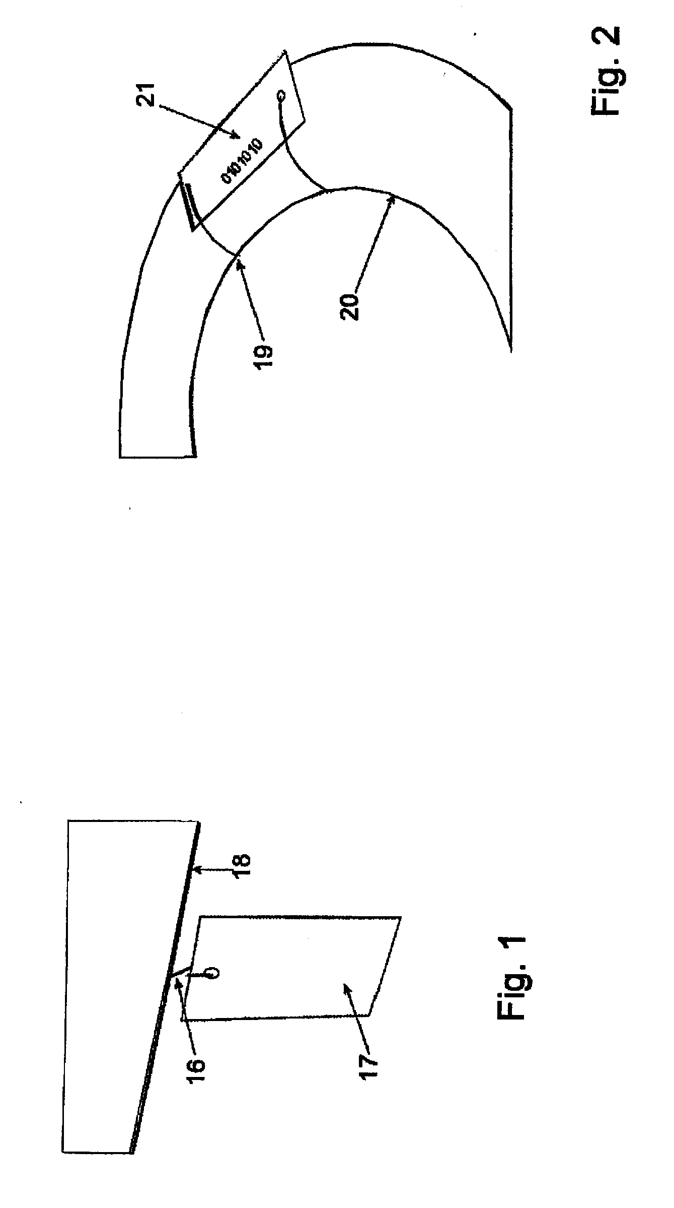
[0031]FIG. 1 shows a tag fixing on a metallic vehicle chassis,

[0032]FIG. 2 shows a tag fixing on a pipe,

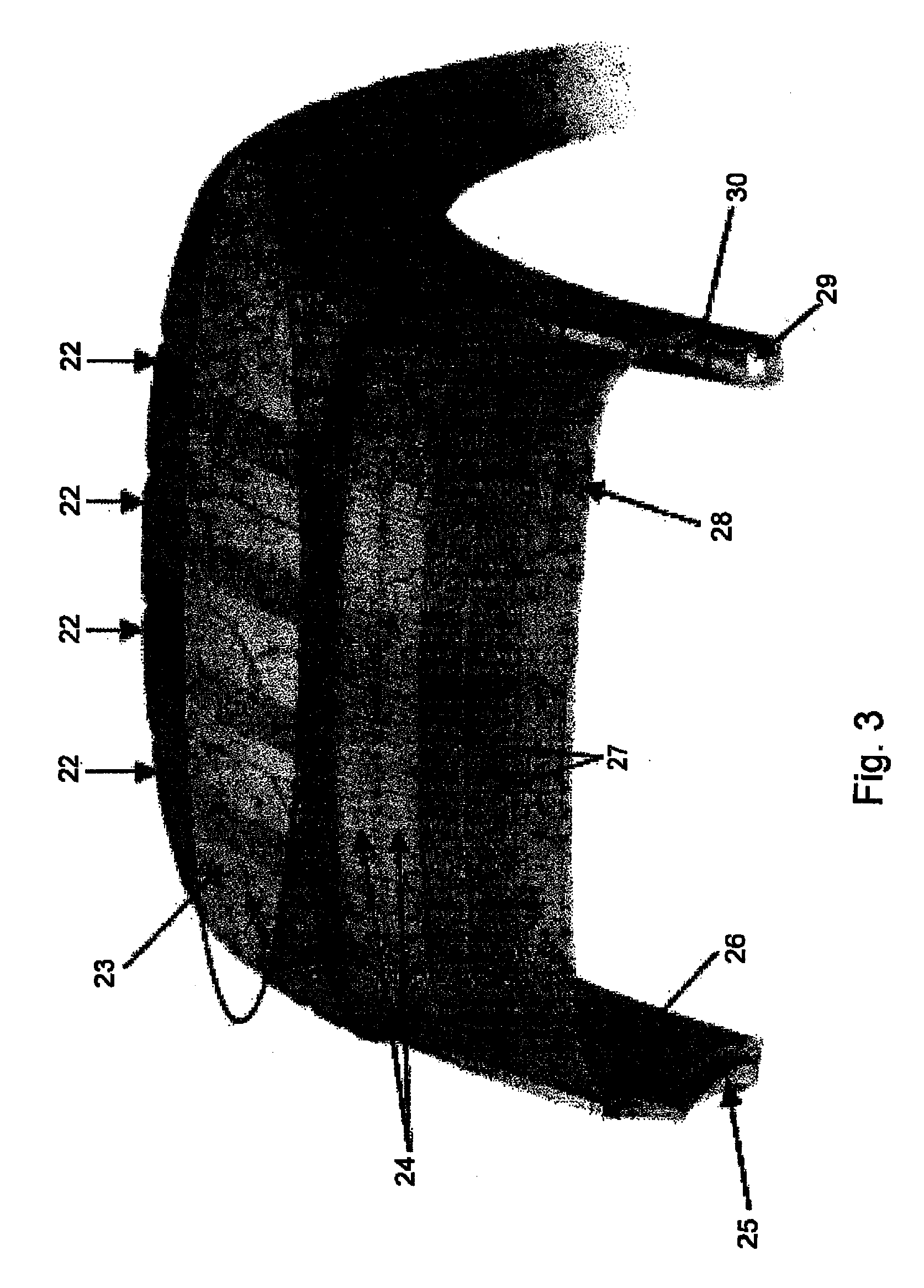
[0033]FIG. 3 shows a structure of a tire,

[0034]FIG. 4 shows a structure of a tire in a cross-sectional view,

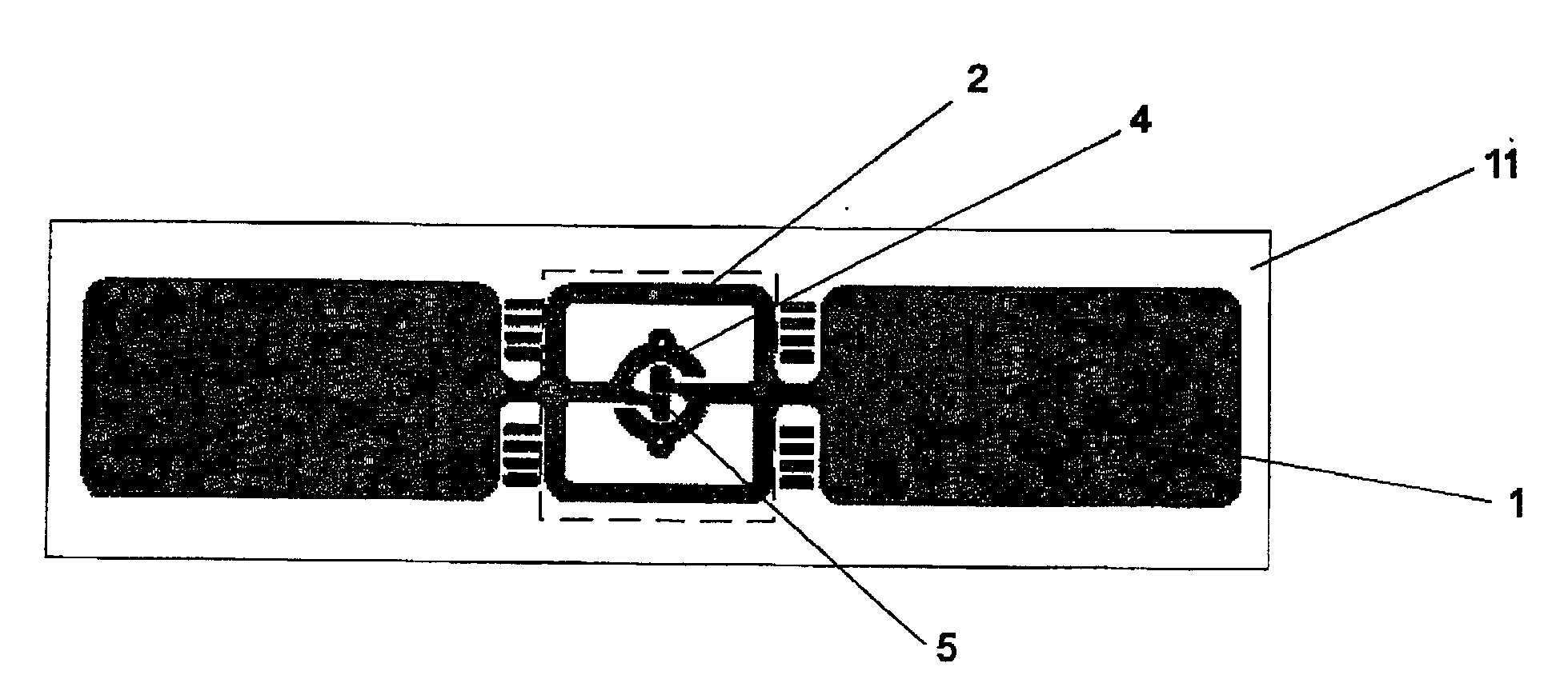
[0035]FIG. 5 shows a possible antenna structure for a high temperature RFID tag from above, especially useful as a free hanging high temperature tag,

[0036]FIG. 6 shows another possible antenna structure for a high temperature RFID tag from above, especially useful as a tire tag,

[0037]FIG. 7 shows yet another possible antenna structure for a high temperature RFID tag from above,

[0038]FIG. 8 shows yet another possible antenna structure for a high temperature RFID tag from above, especially useful as a tire tag,

[0039]FIG. 9 shows details of the tag of FIG. 6,

[0040]FIG. 10 shows a cross-sectional view of the tag at the chip,

[0041]FIG. 11a shows a cross-sectional view of a high temperature RFI...


PUM


Abstract

The present invention relates to an RFID tag comprising a heat-resistant substrate (11) made of a plastic film and capable of withstanding temperatures up to 200° C., an antenna (1) formed on the surface of the substrate, an integrated circuit on a silicon chip (6) electrically connected to the antenna and a joint for attaching the chip to the substrate so that the chip is capable of connecting electrically to the antenna. The joint is made of an an isotropically conductive adhesive capable of withstanding temperatures up to 200° C. and having a thermal expansion coefficient essentially similar to that of the silicon chip.

Description

FIELD OF THE INVENTION[0001]The present invention relates to an RFID tag (radio frequency identification tag).BACKGROUND OF THE INVENTION[0002]RFID applications in industry concerning high temperature and demanding chemical applications usually require high-cost tags with an expensive but heat-resistant encapsulation. Most of the known industrially manufactured tags for harsh conditions are very expensive printed circuit boards, and they are encapsulated, being thus extremely expensive and rigid.[0003]One special application in the field of the high temperature RFID tags is a tire tag. The tire tag should resist the harsh tire vulcanizing process which involves high temperatures and pressures. The existing tire tags are quite expensive and they comprise heat resistant encapsulations because without special structures the RFID transponder would break down. The tire tags may be embedded in the tire which is a disadvantage because an embedded tag can cause unexpected failure of the tir...

Claims


Application Information

Patent Timeline
IPC IPC(8): G06K19/077
CPCG06K19/0773G06K19/07745G06K19/0775H01L2224/16225H01L2224/32225H01L2224/73204H01L2924/00H01L2924/00014H01L2924/00011H01L2224/0401
Inventor RITAMAKI, MATTIAHOKAS, HEIKKIMIETTINEN, JARKKOLUOMA-AHO, HANNA
Owner CONFIDEX OY
Why Eureka
Try Eureka