
Heater pocket for a household appliance

a heater pocket and household appliance technology, applied in the field of household appliances, can solve the problems of reducing or limiting the heat distribution from the heater coil to the washing liquid reducing or limiting the heat distribution efficiency of the discharge pump, etc., and achieves the effect of affecting the durability and reliability of the washer, and reducing the efficiency of the washer

Inactive Publication Date: 2011-02-03
BSH HOME APPLIANCES CORP
View PDF12 Cites 1 Cited by
  • Summary
  • Abstract
  • Description
  • Claims
  • Application Information

AI Technical Summary

Benefits of technology

[0008]The present invention recognizes that the flow patterns of the washing liquid into, within, and out of the heater pocket can affect the heat distribution from the heater coils to the washing liquid, and thus the efficiency of the washer. The present invention further recognizes that the deposition and accumulation of debris below, on, or around the heater coils can affect the heat distribution from the heater coils to the washing liquid, thereby reducing the efficiency of the washer. The deposition and accumulation of debris below, on, or around the heater coils also can result in early failure of the heating element, thereby affecting the durability and reliability of the washer.
[0009]As explained above with reference to FIG. 8, in many conventional washers, the heater pocket 1300 has a generally rectangular, box-shaped design in which the first sidewall 1302 is substantially parallel to the second sidewall 1304, and the first and second sidewalls 1302, 1304 are substantially perpendicular to the bottom wall 1306. The conventional heater pocket may result in irregular flow patterns below and around the heating element, thereby reducing or limiting the heat distribution from the heater coils to the washing liquid.
[0010]For example, the sharp edges of the heater pocket 1300 where the sidewalls 1302, 1304 meet the tub 1210, as well as the vertical sidewalls 1302, 1304 of the heater pocket 1300 themselves, can induce irregular and heavily disturbed flow of the washing liquid under and around the heater coils 404. Also, the conventional heater pocket may reduce or limit the drainage efficiency to the discharge pump. The dynamics of the drum motion (i.e., rotation or oscillation) also can induce irregular flow patterns of the washing liquid below and around the heating element. The washing liquid can flow in a plurality of directions and at various velocities. Thus, with the conventional heater pocket 1300, there may be, for example, areas having irregular flow, areas in which the flow velocity is reduced, and / or stagnant areas (i.e., areas of minimal or no flow) below or around the heater coils 404. As a result, the efficiency of the heat distribution from the heater coils 404 to the washing liquid can be reduced. Also, the time to heat the washing liquid in the tub can be increased.

Problems solved by technology

The deposition and accumulation of debris below, on, or around the heater coils also can result in early failure of the heating element, thereby affecting the durability and reliability of the washer.
The conventional heater pocket may result in irregular flow patterns below and around the heating element, thereby reducing or limiting the heat distribution from the heater coils to the washing liquid.
Also, the conventional heater pocket may reduce or limit the drainage efficiency to the discharge pump.

Method used


Image

  • Heater pocket for a household appliance
  • Heater pocket for a household appliance
  • Heater pocket for a household appliance

Examples


Embodiment Construction

[0031]The present invention now is described more fully hereinafter with reference to the accompanying drawings, in which embodiments of the invention are shown. This invention may, however, be embodied in many different forms and should not be construed as limited to the embodiments set forth herein; rather, these embodiments are provided so that this disclosure will be thorough and complete, and will fully convey the scope of the invention to those skilled in the art.

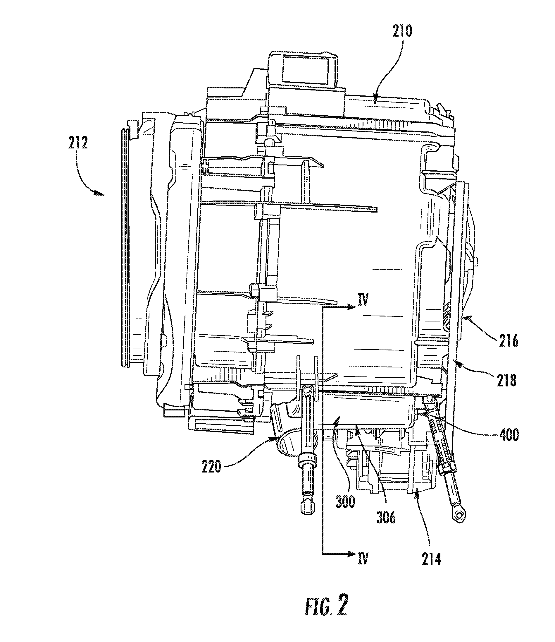
[0032]Referring now to the drawings, FIGS. 1-7 illustrate exemplary embodiments of a household appliance having a heater pocket according to exemplary embodiments of the present invention.

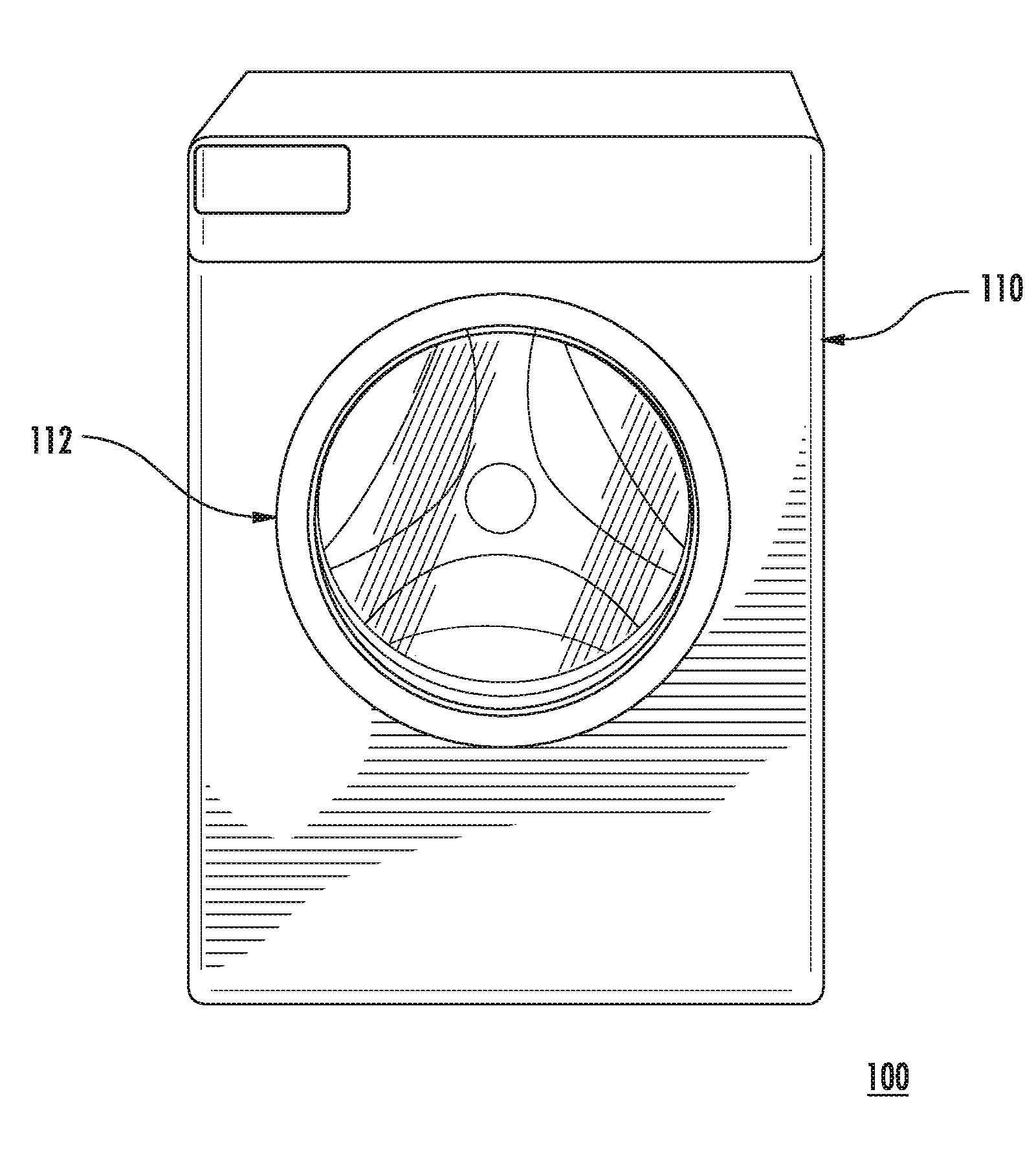
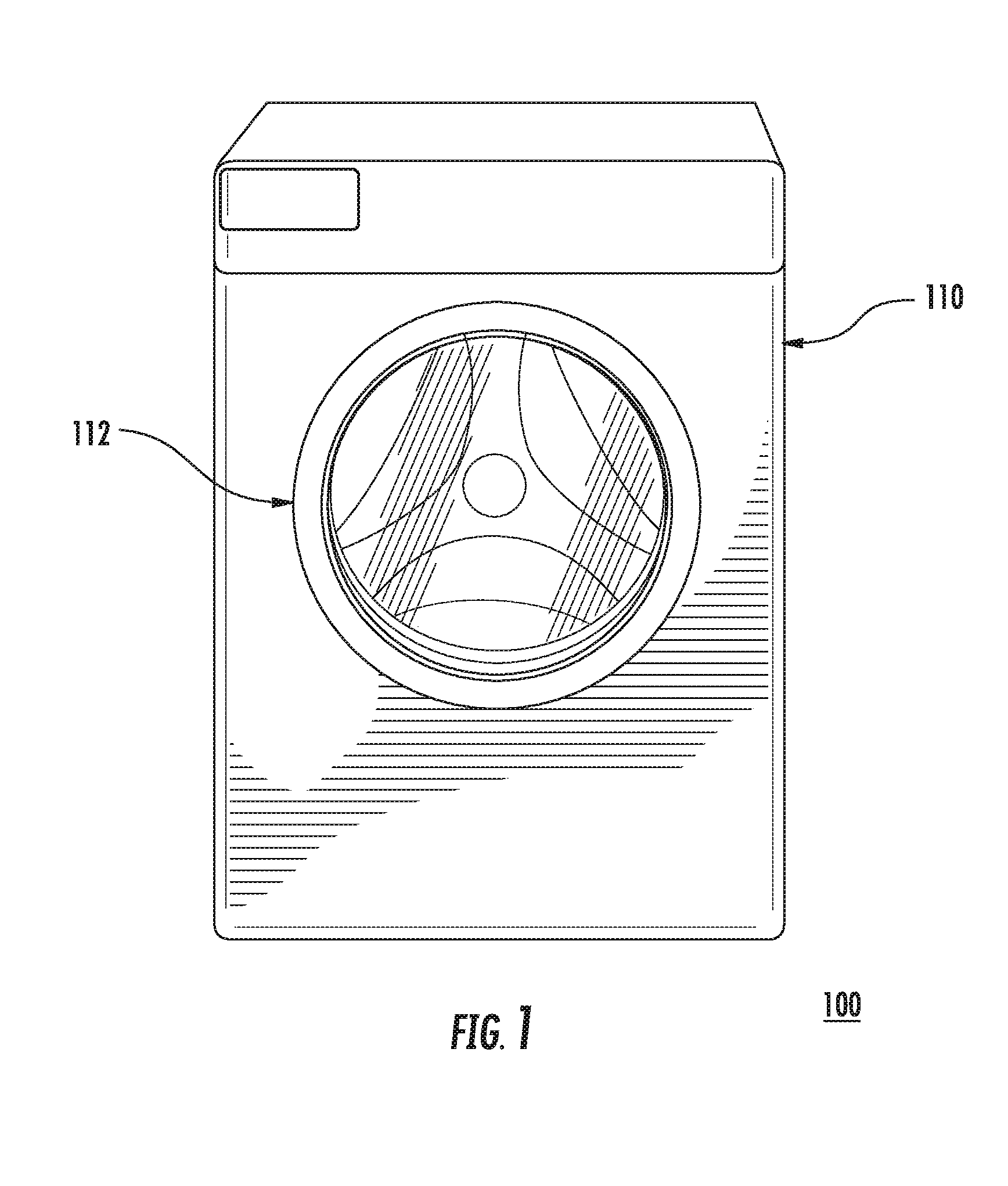
[0033]FIG. 1 illustrates a household appliance 100, such as a front-loading clothes washer, having a housing 110 and a door 112 to provide access to the interior of the appliance housing 110. The household appliance 100 wets the laundry to be washed with washing liquid and mechanically moves the laundry to release contaminants from t...


PUM


Abstract

A household appliance includes a tub having a rotating drum therein, the drum having an axis of rotation. The tub includes a heater pocket integrally formed in a lower portion of the tub, and forming a cavity in fluid communication with the drum. A cross-section of the heater pocket, which is taken in a direction substantially perpendicular to the axis of rotation of the rotating drum, includes a first sidewall, a second sidewall opposed to the first sidewall, and a bottom wall connecting a lower side of the first sidewall to a lower side of the second sidewall, wherein each of the first sidewall and the second sidewall intersects the bottom wall at an angle other than 90°.

Description

FIELD OF THE INVENTION[0001]The present invention is directed toward a household appliance, and more specifically, toward a household appliance having a heater pocket.BACKGROUND OF THE INVENTION[0002]A household appliance, such as a front-loading clothes washer includes a housing having a door providing access to a washing unit in the interior of the appliance housing. The washing unit includes a tub having a cylindrical washing drum rotatably mounted inside the tub. In operation, clothes or laundry are inserted into the washer through the door and placed in the rotating washing drum inside the tub. The household appliance wets the laundry to be washed with washing liquid and mechanically moves the laundry to release contaminants from the laundry. A drive system rotates the washing drum inside the tub about an axis of the drum.[0003]A heating element commonly is provided for heating the washing liquid in the tub of the washer. The heating element may be disposed in a heater pocket o...

Claims


Application Information

Patent Timeline
IPC IPC(8): D06F35/00
CPCD06F39/04D06F37/265
Inventor MURRELL, JONATHANRODRIGUEZ, RAMON
Owner BSH HOME APPLIANCES CORP
Learn More