Light-Emitting Diode Driver Circuit and Lighting Apparatus

a technology of driver circuit and diode, which is applied in the direction of electric variable regulation, process and machine control, instruments, etc., can solve the problem of difficult to maintain the life of the ac-dc converter b>100/b> longer than that of the electrolytic capacitor

Active Publication Date: 2011-02-03
SEMICON COMPONENTS IND LLC
View PDF7 Cites 25 Cited by
  • Summary
  • Abstract
  • Description
  • Claims
  • Application Information

AI Technical Summary

Benefits of technology

[0010]A light-emitting diode driver circuit according to an aspect of the present invention, comprises: a first rectifier circuit configured to output a first rectified voltage obtained by rectifying an AC voltage; a transformer including a primary coil provided on a primary side, a secondary coil provided on a secondary side, and an auxiliary coil inductively coupled to the primary coil or the secondary coil, the primary coil configured to be applied with the first rectified voltage; a transistor connected in series to the primary coil to control a current passing through the primary coil; a second rectifier circuit configu

Problems solved by technology

As such, an electrolytic capacitor having a life shorter than that of a ceramic capacitor, etc., is used in the AC-DC converter 100, whic

Method used


Image

  • Light-Emitting Diode Driver Circuit and Lighting Apparatus
  • Light-Emitting Diode Driver Circuit and Lighting Apparatus
  • Light-Emitting Diode Driver Circuit and Lighting Apparatus

Examples


Embodiment Construction

[0021]At least the following details will become apparent from descriptions of this specification and of the accompanying drawings.

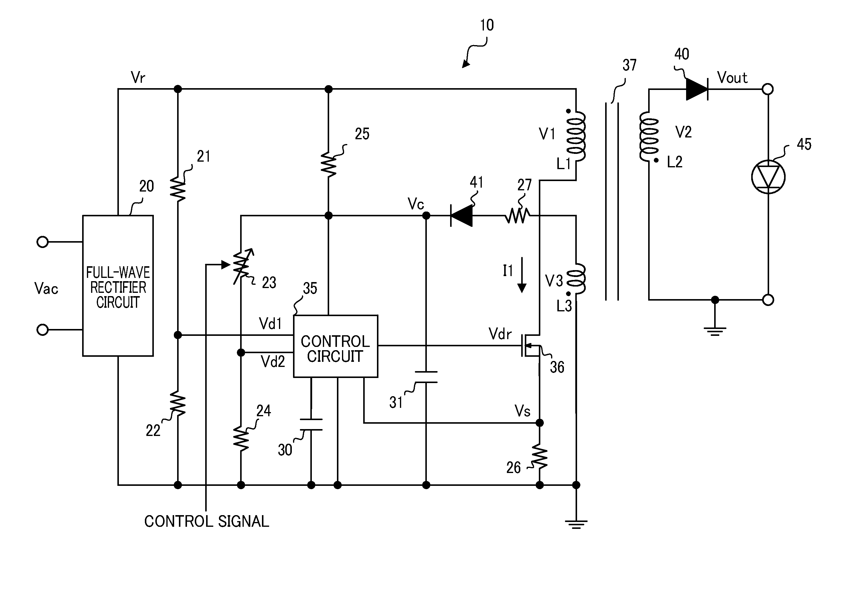
[0022]FIG. 1 depicts a configuration of an LED driver circuit 10 according to an embodiment of the present invention. The LED driver circuit 10 is a circuit configured to generate an output voltage Vout for driving an LED 45 out of an AC voltage Vac from a commercial power supply. The LED driver circuit 10 includes a full-wave rectifier circuit 20, resistors 21 to 27, capacitors 30 and 31, a control circuit 35, a power MOSFET 36, a transformer 37, and diodes 40 and 41. The full-wave rectifier circuit 20 (first rectifier circuit) full-wave rectifies the input AC voltage Vac, to output a rectified voltage Vr.

[0023]The resistors 21 and 22 output to the control circuit 35 a divided voltage Vd1 obtained by dividing the rectified voltage Vr, and resistors 23 and 24 output to the control circuit 35 a divided voltage Vd2 obtained by dividing a charging voltage V...


PUM


Abstract

A light-emitting diode driver circuit includes: a first-rectifier circuit to output a first-rectified voltage; a transformer including primary and secondary coils and an auxiliary coil inductively coupled to the primary or secondary coils, the primary coil being applied with the first-rectified voltage; a transistor connected in series to the primary coil; a second-rectifier circuit to output a second-rectified voltage obtained by rectifying a voltage generated in the auxiliary coil; a capacitor to be charged with the second-rectified voltage; and a control circuit to control on and off of the transistor based on a charging voltage of the capacitor so that the charging voltage becomes equal to a predetermined voltage, the secondary coil outputting a voltage that varies with a frequency corresponding to a frequency of the first-rectified voltage and that corresponds to a turns ratio between the primary and secondary coils, as a voltage for driving a light-emitting diode.

Description

CROSS-REFERENCE TO RELATED APPLICATION[0001]This application claims the benefit of priority to Japanese Patent Application No. 2009-178973, filed Jul. 31, 2009, of which full contents are incorporated herein by reference.BACKGROUND OF THE INVENTION[0002]1. Field of the Invention[0003]The present invention relates to a light-emitting diode driver circuit and a lighting apparatus.[0004]2. Description of the Related Art[0005]A certain type of a lighting apparatus employing a light-emitting diode (hereinafter, referred to as “LED”) is turned on with a power voltage from a commercial power supply. Generally, in such a lighting apparatus, a DC voltage for driving the LED is generated out of an AC voltage from the commercial power supply, using an AC-DC converter (see Japanese Patent Application Laid-Open Publication No. 2009-134945). FIG. 8 depicts a common configuration of an AC-DC converter. An AC-DC converter 100 is a circuit that generates a desired DC output voltage Vout out of an AC...

Claims


Application Information

Patent Timeline
IPC IPC(8): H05B37/02
CPCH05B33/0815H05B45/3725
Inventor HORIUCHI, FUMIOIMAIZUMI, TORUKUSABE, TAKAYA
Owner SEMICON COMPONENTS IND LLC
Why Eureka
Try Eureka