Eureka AIR delivers breakthrough ideas for toughest innovation challenges, trusted by R&D personnel around the world.

Two-stage switching power supply

a power supply and two-stage technology, applied in the field of power supply, can solve the problems of low conversion efficiency of linear power supply to meet power-saving requirements, output voltage cannot be maintained at the rated voltage value, and the linear power supply is not applicable to a slim-type electronic device, etc., to achieve high electricity consumption amount of system circuit and high operating efficiency

Inactive Publication Date: 2011-02-03
DELTA ELECTRONICS INC
View PDF16 Cites 42 Cited by
  • Summary
  • Abstract
  • Description
  • Claims
  • Application Information

AI Technical Summary

Benefits of technology

[0007]It is an object of the present invention to provide two-stage switching power supply having high operating efficiency when the electricity consumption amount of the system circuit is high or low.

Problems solved by technology

Since the linear power supply has bulky volume, the linear power supply is not applicable to a slim-type electronic device.
In addition, the converting efficiency of the linear power supply is too low to comply with the power-saving requirements.
If the input AC voltage is subject to a sudden variation or interruption, the output voltage is also subject to a sudden variation or interruption, and thus the output voltage fails to be maintained at the rated voltage value.
In addition, if the input AC voltage is subject to a sudden variation or interruption, the output voltage is rapidly decreased.
As such, the operating efficiency of the second-stage power circuit is usually insufficient.

Method used


Image

  • Two-stage switching power supply
  • Two-stage switching power supply
  • Two-stage switching power supply

Examples


Embodiment Construction

[0019]The present invention will now be described more specifically with reference to the following embodiments. It is to be noted that the following descriptions of preferred embodiments of this invention are presented herein for purpose of illustration and description only. It is not intended to be exhaustive or to be limited to the precise form disclosed.

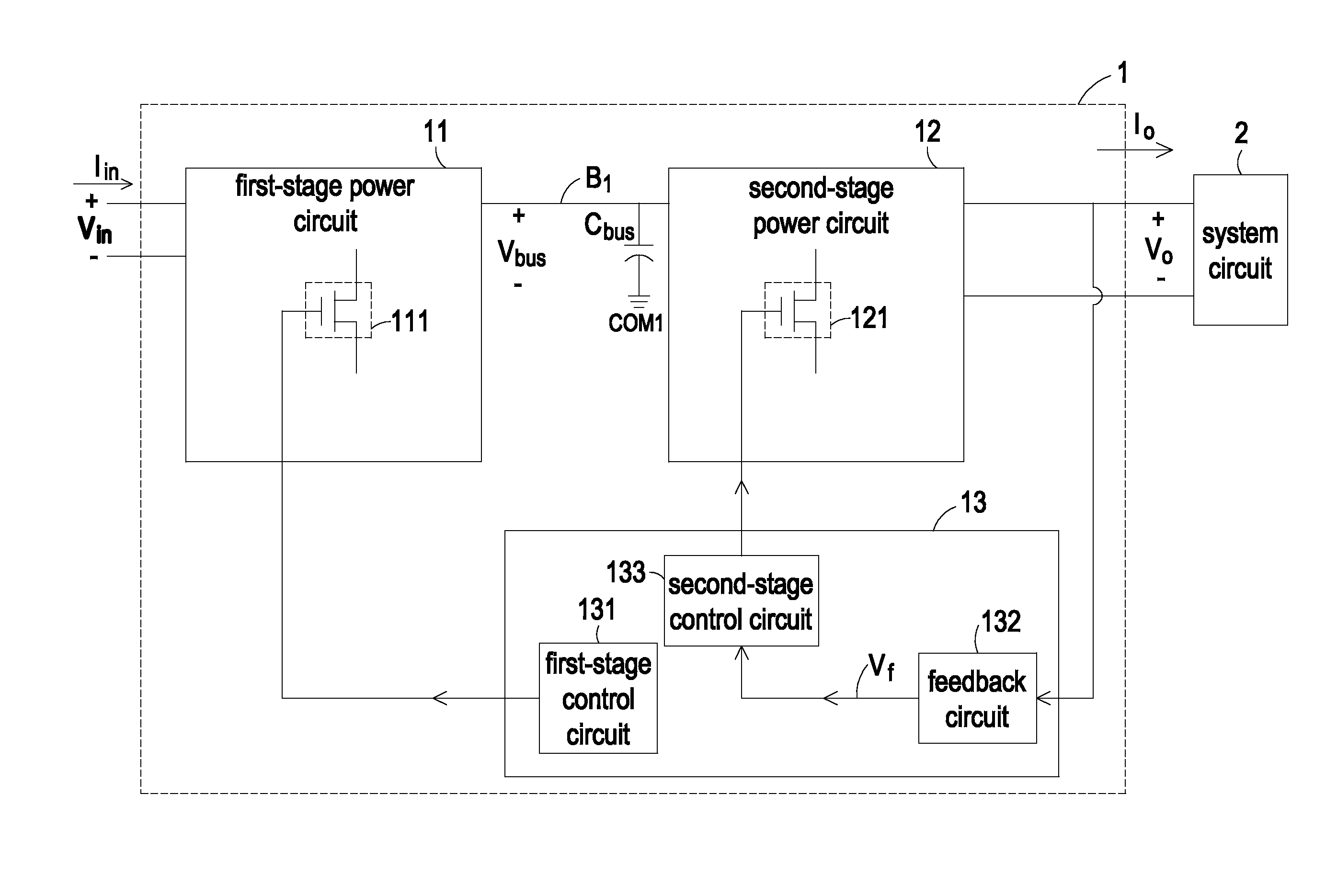
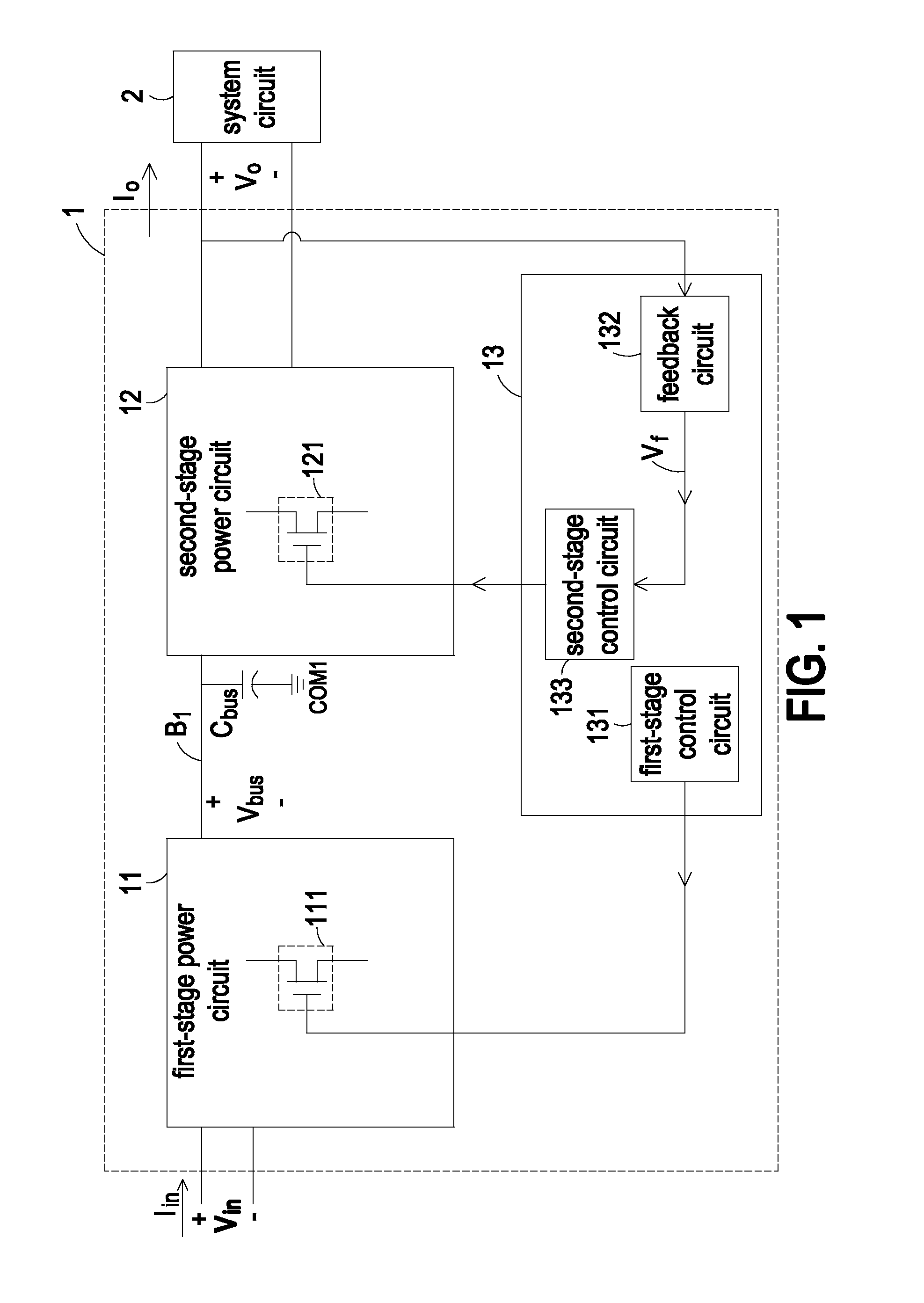
[0020]FIG. 1 is a schematic circuit diagram of a two-stage switching power supply according to an embodiment of the present invention. The two-stage switching power supply 1 is used for receiving an input voltage Vin and generating an output voltage Vo or an output current Io to a system circuit 2 of an electronic device. The two-stage switching power supply 1 comprises a first-stage power circuit 11, a second-stage power circuit 12, a power control unit 13 and a bus capacitor Cbus.

[0021]The first-stage power circuit 11 comprises a first switching circuit 111. The control terminal of the first-stage power circuit 11 is connected ...


PUM


Abstract

A two-stage switching power supply includes a first-stage power circuit, a bus capacitor, a second-stage power circuit and a power control unit. The first-stage power circuit is connected to a power bus for receiving an input voltage, and includes a first switching circuit. The input voltage is converted into a bus voltage by alternately conducting and shutting off the first switching circuit. The second-stage power circuit is connected to the power bus for receiving the bus voltage, and includes a second switching circuit. The power control unit is used for controlling operations of the first switching circuit and the second switching circuit. The bus voltage is dynamically adjusted according to electricity consumption amount of the system circuit under control of the power control unit. An operating mode of the second switching circuit of the second-stage power circuit is changed according to the electricity consumption amount of the system circuit.

Description

FIELD OF THE INVENTION[0001]The present invention relates to a power supply, and more particularly to a two-stage switching power supply.BACKGROUND OF THE INVENTION[0002]With increasing industrial development, diverse electronic devices are used to achieve various purposes. An electronic device comprises a plurality of electronic components. Generally, different kinds of electronic components are operated by using different voltages.[0003]As known, a power supply is essential for many electronic devices such as personal computers, industrial computers, servers, communication products or network products. Usually, the user may simply plug a power supply into an AC wall outlet commonly found in most homes or offices so as to receive an AC voltage. The power supply will convert the AC voltage into a regulated DC output voltage for powering the electronic device. The regulated DC output voltage is transmitted to the electronic device through a power cable.[0004]Generally, power supply a...

Claims


Application Information

Patent Timeline
IPC IPC(8): G05F1/563
CPCH02M2001/0032H02M2001/007Y02B70/16H02M3/3387H02M1/4225H02M3/1584Y02B70/126Y02B70/10H02M1/0032H02M1/007
Inventor WANG, CHENG-PINGLO, CHENG-YIYU, CHANG-CHIEH
Owner DELTA ELECTRONICS INC
Why Eureka
Eureka Blog
Learn More