Method, system and computer program product for producing a test article having embedded features for nondestructive evaluation

a technology of non-destructive evaluation and test articles, applied in probabilistic cad, instruments, computing, etc., can solve the problems of difficult to bury a calibration target in such a reference standard without also removing additional part materials, and the geometry, location and orientation of the calibration target are limited, so as to achieve the the possible geometry of the test article. , the effect of reducing the probability of detection

Inactive Publication Date: 2011-02-03
GENERAL ELECTRIC CO
View PDF11 Cites 19 Cited by
  • Summary
  • Abstract
  • Description
  • Claims
  • Application Information

AI Technical Summary

Problems solved by technology

The problem, however, is that it is difficult to produce a reference standard with calibration target(s) of the optimum geometry, location and orientation necessary to reproduce the actual component configuration, especially for components with complex geometries.
Furthermore, it is difficult to bury a calibration target in such a reference standard without also removing additional part material; because conventional machining must proceed from the surface of the test article.
This problem places considerable limitations on the possible geometry of the test article as well as the geometry, location and orientation of the calibration targets within the test article.
The location of interest is generally coincident with the region of highest in-service stress, where the presence of a flaw of sufficient size will eventually result in failure of the component.
Another problem with the conventional POD approach is that there is significant uncertainty as to the actual location and geometry of the flaws found during post-manufacture or in-service NDE inspections.
The repeated sequential sectioning destroys the flaw and the test sample in the process, so serial polishing is not a viable method to characterize flaws for use in POD analyses.

Method used


Image

  • Method, system and computer program product for producing a test article having embedded features for nondestructive evaluation
  • Method, system and computer program product for producing a test article having embedded features for nondestructive evaluation
  • Method, system and computer program product for producing a test article having embedded features for nondestructive evaluation

Examples


example 1

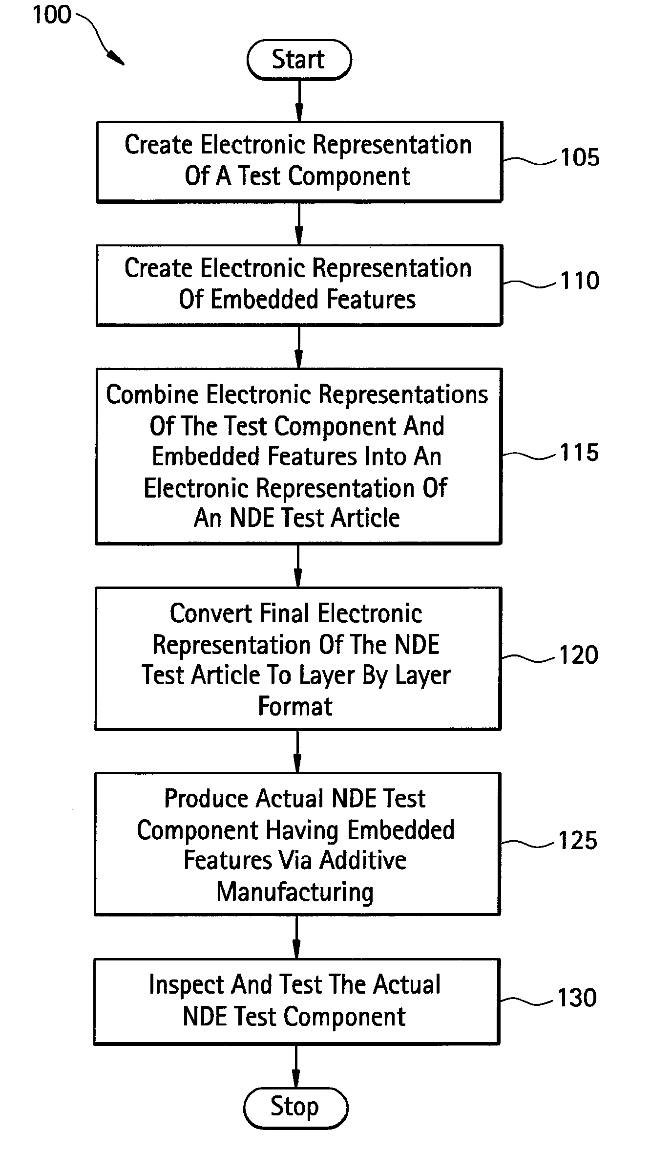
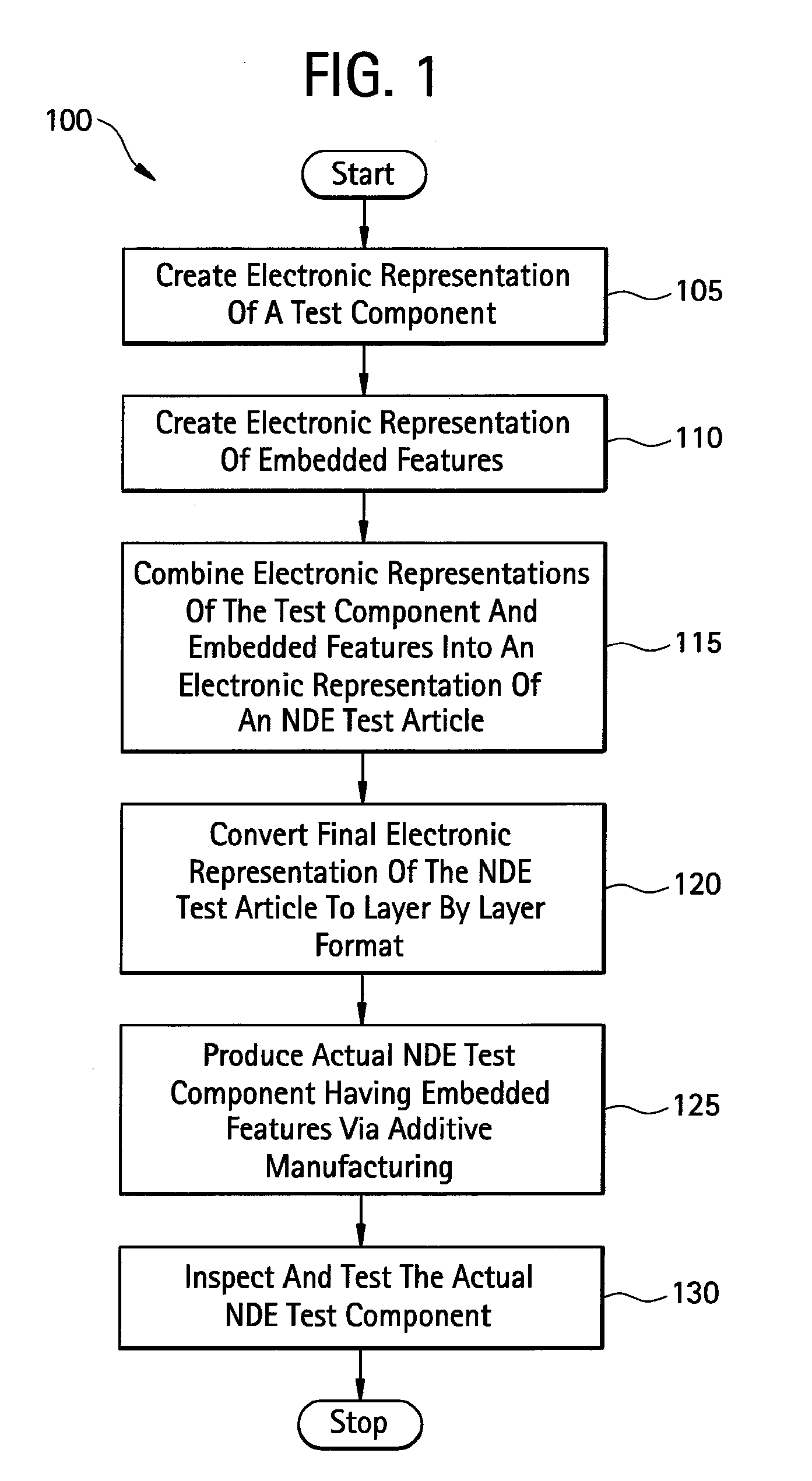
[0046]The method 100 can be applied to the case of a test article including a rectangular block 25 mm long×15 mm wide×16.5 mm tall.

[0047]FIG. 2 illustrates an electronic representation 200 (e.g., a CAD file) of the 3D geometry of a test object produced at block 105 of FIG. 1. In this example, as described above, the test object is a rectangular block 205 that is 25 mm long×15 mm wide×16.5 mm tall.

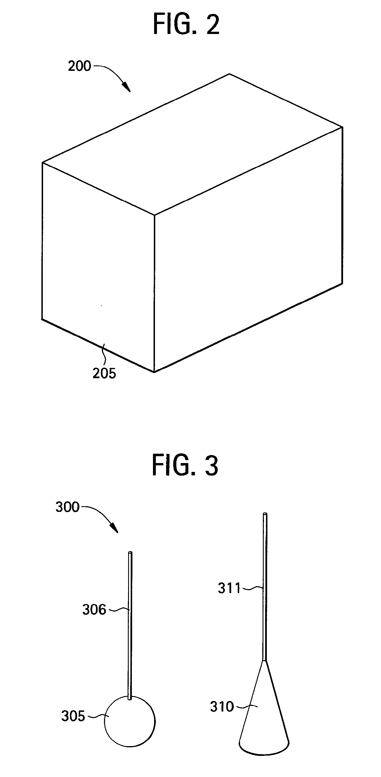
[0048]FIG. 3 illustrates an electronic representation 300 (e.g., a CAD file) of the 3D geometry of one or more calibration targets generated at block 110 of FIG. 1. In this example, the one calibration target is a sphere 305 that is 0.125″ (3.175 mm) in diameter and the second calibration target is a cone 310 with a base diameter of 0.125″ (3.175 mm). Each target is joined to a cylinder 306, 311 that is 0.2 mm in diameter to connect them to the surface of the block 205 to mark the locations.

[0049]FIG. 4 illustrates the combined electronic representations 400 of the electronic representation...

example 2

[0054]The method 100 can also be applied to the simple case of a POD standard including a pipe geometry (i.e., the test article) with an inside diameter (ID) of 20 mm and an outside diameter (OD) of 40 mm. This POD standard is produced to include several half-penny thin notches (designed to simulate axially oriented cracks) connected to the ID surface. Four different thin notches with radii of 2.0, 4.0, 6.0 and 8.0 mm, respectively, are produced in this sample during the manufacturing. The thickness for all of the notches is 0.100 mm.

[0055]FIG. 10 illustrates an electronic representation 1000 of a POD sample as produced at block 105 of FIG. 1. As such, the POD sample is generated as an electronic representation 1000 (e.g., a CAD file) of the 3D geometry of a test component. In this example, the test component is a simulated section of a pipe 25 mm long with an outside diameter (OD) 1005 of 40 mm and an inside diameter (ID) 1010 of 20 mm. The electronic representation 1000 might incl...


PUM


Abstract

A method in a computer system having a display for producing a representation of an article having embedded features including calibration target(s) or simulated defect(s) on the display. The method can include generating a representation of a test component on the display, generating a representation of embedded features on the display and combining the representations of the test component and the embedded features on the display to generate a combined representation. The method can further include converting the combined representation to a layer-by-layer format including manufacturing parameters for additive manufacturing, and producing the test article with an additive manufacturing process.

Description

BACKGROUND OF THE INVENTION[0001]The subject matter disclosed herein relates to nondestructive evaluation (NDE) and probability of detection and, more particularly, to designing and manufacturing of NDE test articles having embedded features such as calibration targets or simulated defects.[0002]Reference standards with well-defined precision geometries of both a test article and calibration target(s) are widely used in all methods of nondestructive evaluation (NDE) for a wide range of applications. NDE is also known as non-destructive testing (NDT) and non-destructive inspection (NDI). Such inspection methods are employed, for example, to validate the quality of a particular component. To employ such methods reliably, a representative reference standard is inspected to establish the inspection response to a known target, such as a flat bottom-, or round bottom-hole, in the case of many ultrasonic nondestructive evaluation methods. It is desirable that the calibration target reside ...

Claims


Application Information

Patent Timeline
Patent Type & Authority Applications(United States)
IPC IPC(8): G06F19/00
CPCG06F2217/10G06F17/50B33Y50/00G06F2111/08G06F30/00
Inventor ROSE, CURTIS WAYNEDEATON, JR., JOHN BRODDUS
Owner GENERAL ELECTRIC CO
Why Eureka
Try Eureka