Double Closed Hydraulic Mould Stand

a double-closed, hydraulic technology, applied in forging/pressing/hammering apparatus, manufacturing tools, forging/hammering/pressing machines, etc., can solve the problems of small and unstable clamping force, difficult cross-axle forging to fall down, processing and installation difficulties, etc., to achieve great and stable clamping force, wide process application range, easy to process, install and maintain

Active Publication Date: 2011-02-10
JIANGSU PACIFIC PRECISION FORGING +1
View PDF5 Cites 10 Cited by
  • Summary
  • Abstract
  • Description
  • Claims
  • Application Information

AI Technical Summary

Benefits of technology

[0021]Compared with an existing double closed hydraulic mould stand for cross-axle flashless precision forging in Precision Forging Mould Manual, in the present invention, a clamping force is generated by using pressure oil in an up piston cylinder and a down piston cylinder, so the clamping force is great and stable, and the process application range is wide. Compared with the double closed hydraulic mould stand for cross-axle flashless die forging proposed by Hyoji Yoshimuya et al., in the present invention, both the up piston cylinder and the down piston cylinder have a combined structure of a cylinder bottom, a cylinder body, a cylinder cover, and an annular fixing ring. The up cylinder body and the down cylinder body are the up mould plate and the down mould plate. Such a combined structure can be easily processed, installed, and maintained. A cylindrical helical spring is installed between the up cylinder bottom and the annular piston in the up piston cylinder. When the mould forging is ended and the up concave mould and the up punch pin return upward together, the up concave mould is repositioned downward rapidly, so vacuum oil absorption is generated at an up cavity of the up piston cylinder. A cylindrical helical spring and a nitrogen gas spring are installed between the down cylinder bottom and the annular piston in the down cylinder, when the mould forging is ended, the two springs push the down concave mould, the down concave mould bed piece and the intermediate floating plate and the down concave mould seat integrally secured upward rapidly, so the return force is greater than that when only the nitrogen gas spring is adopted, and the return speed is higher. In the present invention, a contact surface between the up bearing support and the up hinge base is a plane, which can be processed more easily than the arc surface, and the abrasion is uniform, so as to keep a size of the contact area unchanged.
[0022]When the present invention is used, the up bottom plate is fixed at a bottom surface of a sliding block of the single-acting hydraulic press or single-acting mechanical press. The down bottom plate is fixed on a surface of a worktable of the single-acting hydraulic press or the mechanical press. The left and right stop blocks are disassembled, thus ensuring the use on the mechanical press.
[0023]The up piston cylinder body and the down piston cylinder body according to the present invention adopt a split combined structure, which facilitates manufacturing, installation, and maintenance. The up piston cylinder is repositioned by using a cylindrical spring, and the down piston cylinder is repositioned by using a cylindrical spring and a nitrogen gas spring, so the reposition is strong and fast, which facilitates vacuum oil absorption, power consumption saving, and productivity improvement. A contact between an up hinge base and an up bearing support of the speed ratio mechanism is designed into a plane, which can be easily processed and the abrasion is uniform in use, so that a size of a contact area is constant. The double closed mould stand can be installed on the single-acting hydraulic press for use, and can also be installed on the single-acting mechanical press for use after the stop blocks are disassembled, so the adaptation range is wide.

Problems solved by technology

However, the polyurethane rubber and the helical spring generate a clamping force which is small and unstable.
However, both the up and down cylinders are integral structures, and a bottom shape of the cylinder is complicated, thus causing difficulties in processing and installation.
Once being stuck on the up concave mould and the up punch pin, it is very difficult for the cross-axle forging to fall down.
The up bearing support and the up hinge base are in a semi arc surface contact, which require difficult processing, so a contact area therebetween is easily decreased, and maintenance is difficult.

Method used


Image

  • Double Closed Hydraulic Mould Stand
  • Double Closed Hydraulic Mould Stand
  • Double Closed Hydraulic Mould Stand

Examples


Embodiment Construction

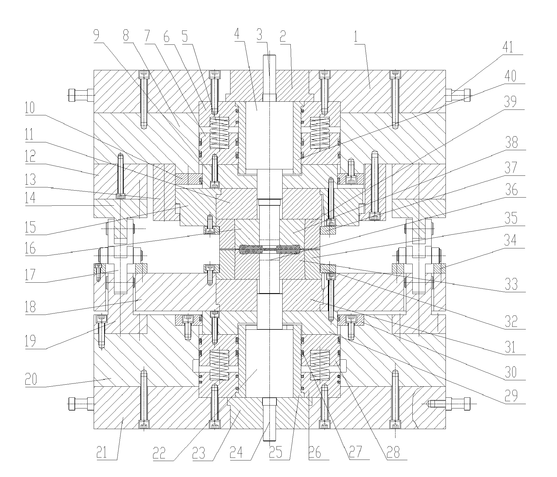
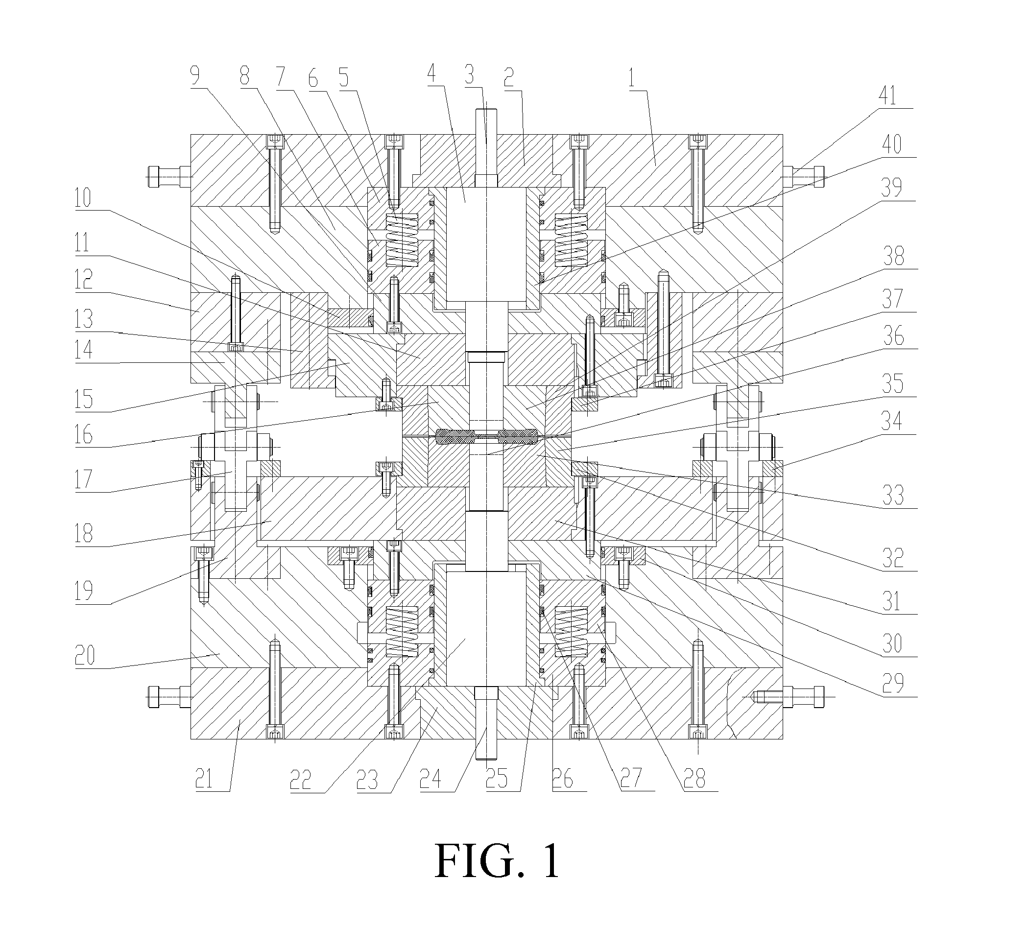
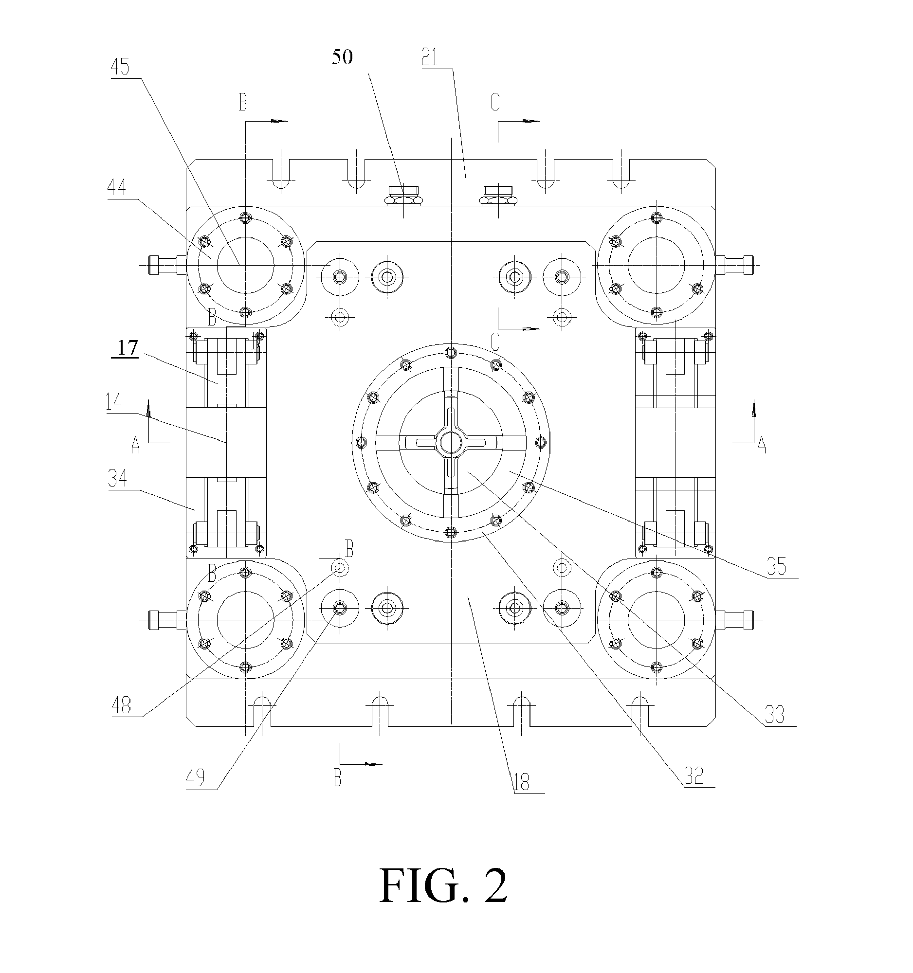
[0029]As shown in FIGS. 1 to 4, a double closed hydraulic mould stand according to the present invention includes an up bottom plate 1, an up bottom plate insert 2, an up pin-lift 3, an up punch pin seat 4, a cylindrical spring 5, an up cylinder bottom 6, an up annular piston 7, an up mould plate 8, an up cylinder cover 9, an up annual ring 10, an up bed piece 11, an up bearing support 12, an up stop sleeve 13, an up hinge base 14, an up concave mould seat 15, an up concave mould 16, a four-bar linkage 17, an intermediate floating plate 18, a down hinge base 19, a down mould plate 20, a down bottom plate 21, a down punch pin seat 22, a down bottom plate insert 23, a down pin-lift 24, a down gliding sleeve 25, a down cylinder bottom 26, a sealing ring 27, a down annular piston 28, a down cylinder cover 29, a down annual ring 30, a down bed piece 31, a down concave mould fixing ring 32, a down concave mould 33, a floating bed piece 34, a down concave mould prestressed ring 35, a down ...


PUM

PropertyMeasurementUnit
speed ratioaaaaaaaaaa
flexibleaaaaaaaaaa
clamping forceaaaaaaaaaa

Abstract

A double closed hydraulic mould stand is provided, which includes an up bottom plate (1), a down bottom plate (21), an up mould plate (8), a down mould plate (20), four guide sleeves (42), four guide columns (45), and a four mechanical linkage velocity ratio mechanism. The four guide sleeves (42) and the four guide columns (45) are distributed symmetrically and slidingly fit each other. An up piston cylinder, a down piston cylinder, an up bed piece (11), a down bed piece (31), an up concave mould seat (15), a down concave mould seat, an up concave mould (16), and a down concave mould (33) are fixed at the up bottom plate and the down bottom plate. An up pin-lift (3), a down pin-lift (24), an up punch pin seat (4), a down punch pin seat (22), an up punch pin (38), and a down punch pin (36) form an up piston and a down piston respectively. The up piston cylinder and the down piston cylinder have a split combined structure, which is convenient for manufacturing, installation, and maintenance. The up piston cylinder is repositioned by using a cylindrical spring. The down piston cylinder is repositioned by using a cylindrical spring and a nitrogen gas spring. The reposition is strong and fast, which facilitates vacuum oil absorption, power consumption saving, and productivity improvement. The present invention can be installed on a single-acting hydraulic press or a single-acting mechanical press for use, and has a wide application range.

Description

BACKGROUND OF THE INVENTION[0001]1. Field of Invention[0002]The present invention relates to a hydraulic device in a forge forming technology.[0003]2. Related Art[0004]Referring to “Precision Forging Mould Manual” (Hu Yamin, China Machine Press, Beijing, 2002), an existing three-pin axle and a small-sized cross-axle double closed mould stand are formed of a mould stand and a flexible clamping device. The mould stand includes an up mould plate, an up concave mould seat, an up punch pin, a down mould plate, a down concave mould seat, a down punch pin, and four sets of symmetrically distributed guide columns and guide sleeves. The flexible clamping device includes cylindrical polyurethane rubber, a retaining ring and a connecting bolt, cylinder helical spring, and a stop bolt. The parts and elements are symmetrically distributed in the up mould plate and the down mould plate. During flashless die forging, the cylinder polyurethane rubber and the cylinder helical spring generate a clamp...

Claims


Application Information

Patent Timeline
Patent Type & Authority Applications(United States)
IPC IPC(8): B21J13/00
CPCB21J9/12B21J13/03B21J13/00
Inventor XIA, HANGUANXIA, JUCHENHU, GUOANWANG, XINYUNJIN, JUNSONGDONG, YI
Owner JIANGSU PACIFIC PRECISION FORGING
Why Eureka
Try Eureka