Oscillation control device

a control device and oscillator technology, applied in the direction of turn-sensitive devices, instruments, vessel construction, etc., can solve the problems of difficult to select the proper values of springs and damping factors, difficult to control the relative movement of the movable object, and high cost of conventional devices, so as to achieve the effect of suppressing the relative movemen

Inactive Publication Date: 2011-02-10
MAEDA TERUO
View PDF4 Cites 9 Cited by
  • Summary
  • Abstract
  • Description
  • Claims
  • Application Information

AI Technical Summary

Benefits of technology

[0007]According to a first aspect of the present invention there is provided an oscillation control device including a base body, a movable object, an inertial mass and a driving mechanism. The movable object is supported to the base body. The inertial mass is capable of applying inertial force to the movable object. The driving mechanism mechanically connects the base body and the inertial mass with each other so that the driving mechanism can drive the inertial mass according to a relative movement of the movable object relative to the base body so that the relative movement can be suppressed due to the inertial force.

Problems solved by technology

However, this conventional device provides a problem in that it is often difficult to select proper values of the springs and damping factors.
When the relative speed therebetween is small, dampers cannot generate sufficient damping forces, so that it is hard to control the relative movement of the movable object, such as the period, the amplitude and the attitude of the oscillation, against the oscillation applied to the movable object and / or the base body.
However, this conventional device costs high.

Method used


Image

  • Oscillation control device
  • Oscillation control device
  • Oscillation control device

Examples


first embodiment

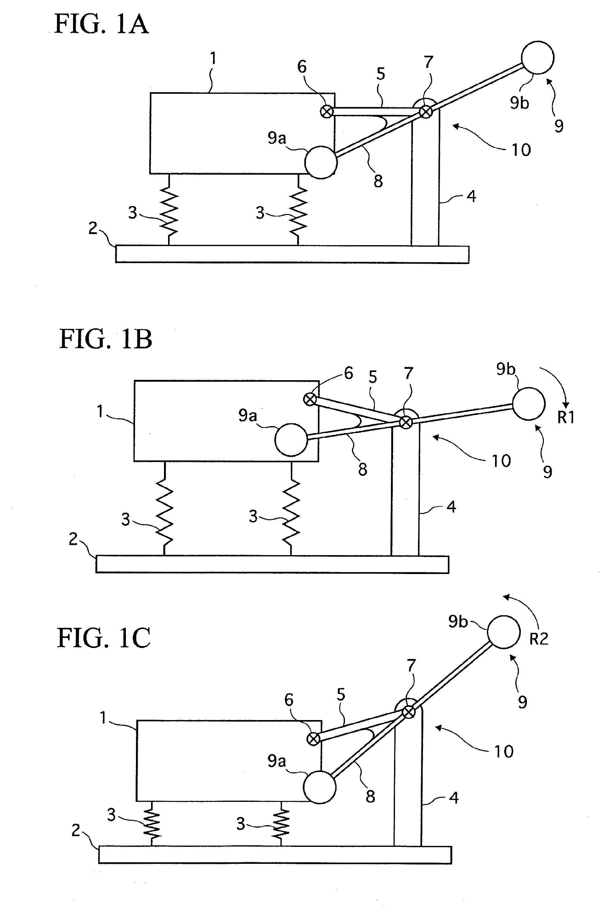
[0022]The oscillation control device of the first embodiment includes a movable object 1, a base body 2, a plurality of springs 3, an inertial mass 9 and a driving mechanism 10.

[0023]The base body 2 is placed on the ground, the water, buildings or the like, and it is constructed so as to move together with a movement thereof relative thereto.

[0024]The springs 3 are arranged apart from each other, fixing the movable object 1 and the base body 2 with each other so that the movable object 1 can be elastically supported over the base body 2 to move relative to the base body 2.

[0025]The base body 2 is fixed at one end portion thereof with a pillar 4, which extends upward from an upper surface of the base body 2. The pillar 4 is provided with a first pivot 7 at its top portion. A connecting link 5 is connected with the first pivot 7 at its one end portion and with a second pivot 6 at its other end portion. The second pivot 6 is provided at one side portion of the movable object 1, so that...

second embodiment

[0035]Next, an oscillation control device of a second embodiment according to the present invention will be described with the accompanying drawings.

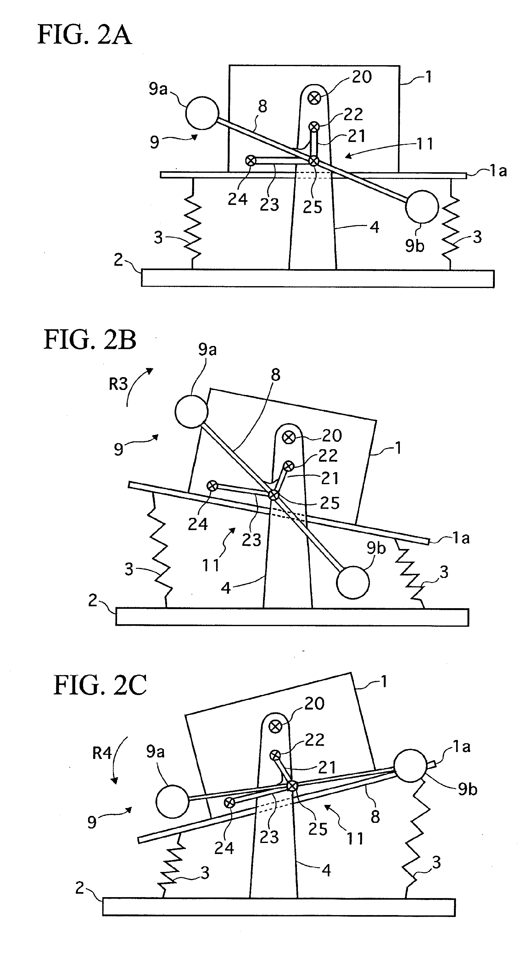
[0036]As shown in FIG. 2A, in the oscillation control device of the second embodiment, a pillar 4 is fixed on a base body 2 at an intermediate portion of the base body 2 to extend upward from its upper surface. The pillar 4 is provided with a third pivot 20 at its top portion and with a fourth pivot 22 under the third pivot 20. The third pivot 20 swingably supports a movable object 1 to the pillar 4.

[0037]A driving mechanism 11 of the second embodiment includes the fourth pivot 22, a fifth pivot 24, a sixth pivot 25, a first swingable link 21 and a second swingable link 23. The first and second swingable links 21 and 23 correspond to first and second link members of the present invention, respectively.

[0038]The first swingable link 21 is connected with the fourth pivot 22 at its one end portion and with the sixth pivot 25 at its other e...

third embodiment

[0047]Next, an oscillation control device of a third embodiment according to the present invention will be described with the accompanying drawings.

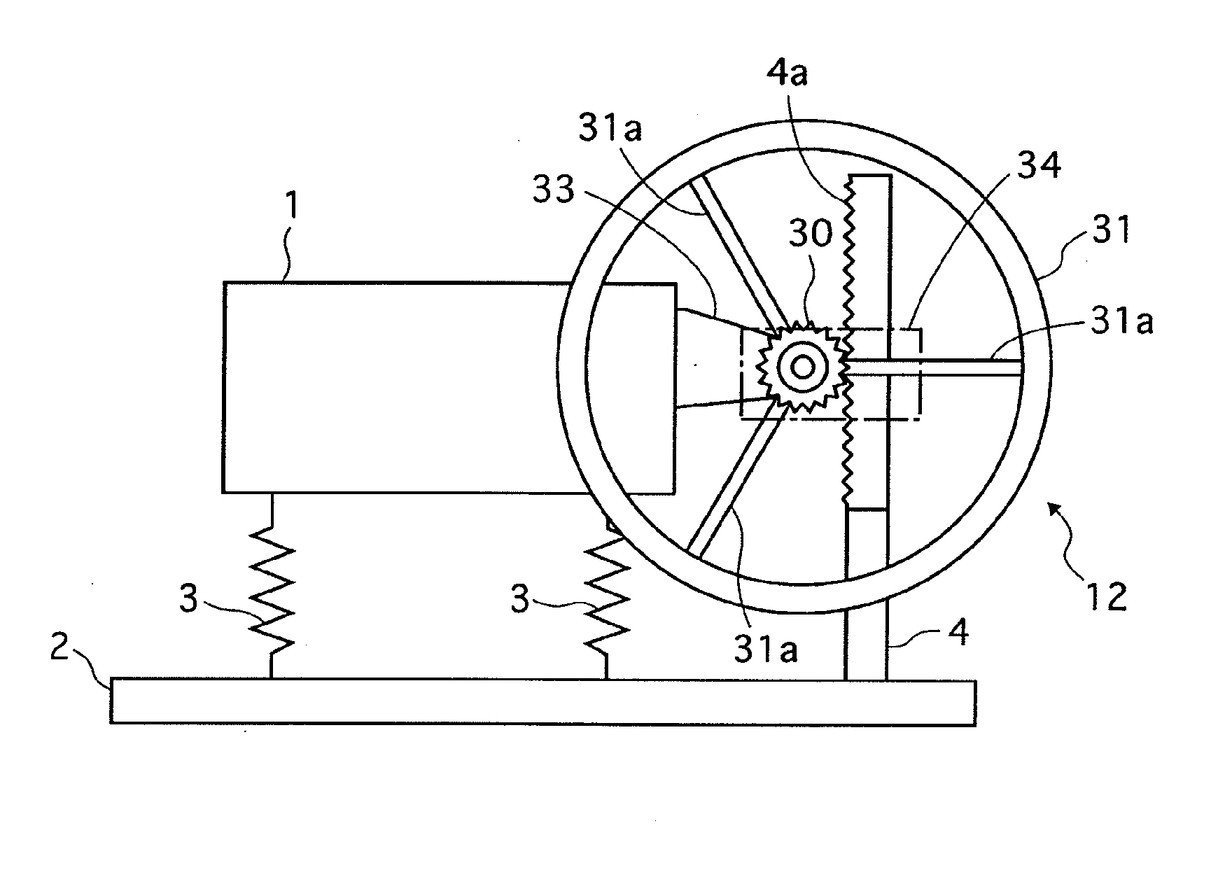
[0048]FIG. 3 illustrates the oscillation control device of the third embodiment, eliminating some parts of a driving mechanism thereof in order to facilitate visualization thereof, while FIG. 4 shows an enlarged cross sectional plan view of a detail construction of the driving mechanism.

[0049]As shown in FIG. 3 and FIG. 4, in the oscillation control device of the third embodiment, the first and second inertial mass 9a and 9b and the beam 8 of the first and second embodiments are replaced by a wheel 31 with three spokes 31a and a hub portion 31b. The hub portion 31b is fixed to a hub portion 30b of a pinion 30, which will be later explained. The spokes 31a may be replaced by a disc portion connecting the hub portion 31b and the wheel 31.

[0050]A pillar 4 is fixed on one end portion of a base body 2, being formed with a rack portion 4a at a...


PUM


Abstract

An oscillation control device includes a base body, a movable object, an inertial mass and a driving mechanism. The movable object is supported to the base body. The inertial mass is capable of applying inertial force to the movable object. The driving mechanism mechanically connects the base body and the inertial mass with each other so that the driving mechanism can drive the inertial mass according to a relative movement between the movable object and the base body so that the relative movement therebetween can be suppressed due to the inertial force.

Description

BACKGROUND OF THE INVENTION[0001]1. Field of the Invention[0002]The present invention relates to an oscillation control device in which a relative movement of a movable object can be controlled relative to a base body that supports the movable object.[0003]2. Description of the Related Art[0004]Various kinds of conventional oscillation control devices are known. For example, using springs and dampers disposed between a movable object and a base body. However, this conventional device provides a problem in that it is often difficult to select proper values of the springs and damping factors. When the relative speed therebetween is small, dampers cannot generate sufficient damping forces, so that it is hard to control the relative movement of the movable object, such as the period, the amplitude and the attitude of the oscillation, against the oscillation applied to the movable object and / or the base body.[0005]On the other hand, it is known to use electronics control for changing att...

Claims


Application Information

Patent Timeline
Patent Type & Authority Applications(United States)
IPC IPC(8): G01C19/56
CPCG05D19/00F16F7/10B63B17/0081
Inventor MAEDA, TERUO
Owner MAEDA TERUO
Why Eureka
Try Eureka