Female terminal and chain terminal thereof

a technology of chain terminals and female terminals, which is applied in the manufacture of contact parts, coupling device connections, and contact member materials, etc. it can solve the problems of affecting the electrical performance of the connector, the inability to meet the requirements of the female terminal, and the inability to meet the requirements of the male terminal, so as to reduce the amount of material used for forming the female terminals, the effect of reducing the pitch of juxtaposed female terminal pieces and enhancing economics

Inactive Publication Date: 2010-08-31
YAZAKI CORP
View PDF15 Cites 7 Cited by
  • Summary
  • Abstract
  • Description
  • Claims
  • Application Information

AI Technical Summary

Benefits of technology

[0009]It is an object of this invention to provide a female terminal structure in which even when a connector is formed into a small-size design, a swinging movement of a male terminal can be suppressed.
[0012]In the construction of the invention, the male terminal inserted in the tubular portion is pressed against inclined inner side surfaces of the tubular peripheral wall by the spring portion, so that the male terminal is supported at three points within the space. Therefore, the male terminal can be held in the space without shaking, and a swinging movement of the male terminal can be prevented. In the female terminal, the lengths of the shorter and longer sides are determined according to the maximum width of the male terminal, and merely by doing so, a small-size design of the connector can be easily achieved. Furthermore, the tubular portion is asymmetrical in the upward-downward direction, and therefore a reverse insertion prevention mechanism doe not need to be provided at the terminal, and the production cost can be reduced.
[0014]In the chain terminal including the plurality of female terminal pieces each adapted to be formed into the female terminal of the invention, the tubular portion of the female terminal formed by the female terminal piece has the trapezoidal cross-section. Therefore, the overall length of the periphery of the tubular portion (not yet subjected to a bending operation) in its developed condition (that is, the width of the tubular portion developed in the longitudinal direction of the carrier) is shorter as compared with a usual female terminal in which a tubular portion has a rectangular cross-section. Therefore, a pitch of the juxtaposed female terminal pieces can be reduced, and therefore the amount of the material used for forming the female terminals can be reduced, and the economy can be enhanced.
[0015]In the present invention, even when the connector is formed into a small-size design, a swinging movement of the male terminal can be suppressed.

Problems solved by technology

Under the existing circumstances, however, a small-width design of a receiving portion of a female terminal for receiving the male terminal has been less advanced as compared with the small-width design of the male tab.
When the clearance, formed upon reception of the male tab in the receiving portion, thus increases, it is feared that the electrical performance of the connector may be affected.
For example, the male tab received in the receiving portion is liable to shake because of the formation of the clearance, and therefore the male tab swings or oscillates in a longitudinal direction, and as a result wear due to a sliding movement is promoted, or mating contacts are displaced with respect to each other, so that the electrical connection may be liable to become incomplete.
Here, in the case where the clearance between the male tab and each curled portion is decreased, the curled portions tend to become upstanding, so that distal ends of the bent portions thereof can not be pressed into contact with the male tab.
Therefore, the terminal structure of JP-A-2001-167834 has a problem that in the case where the terminal is formed into a small-size design, the terminal is liable to shake because of the swinging movement of the male tab.

Method used


Image

  • Female terminal and chain terminal thereof
  • Female terminal and chain terminal thereof
  • Female terminal and chain terminal thereof

Examples


Embodiment Construction

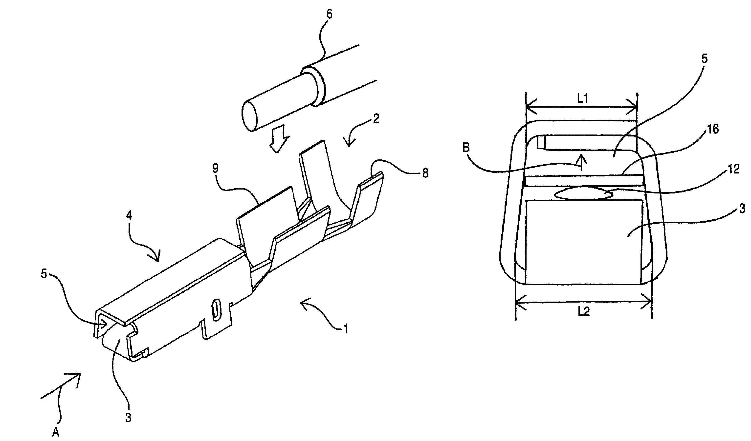
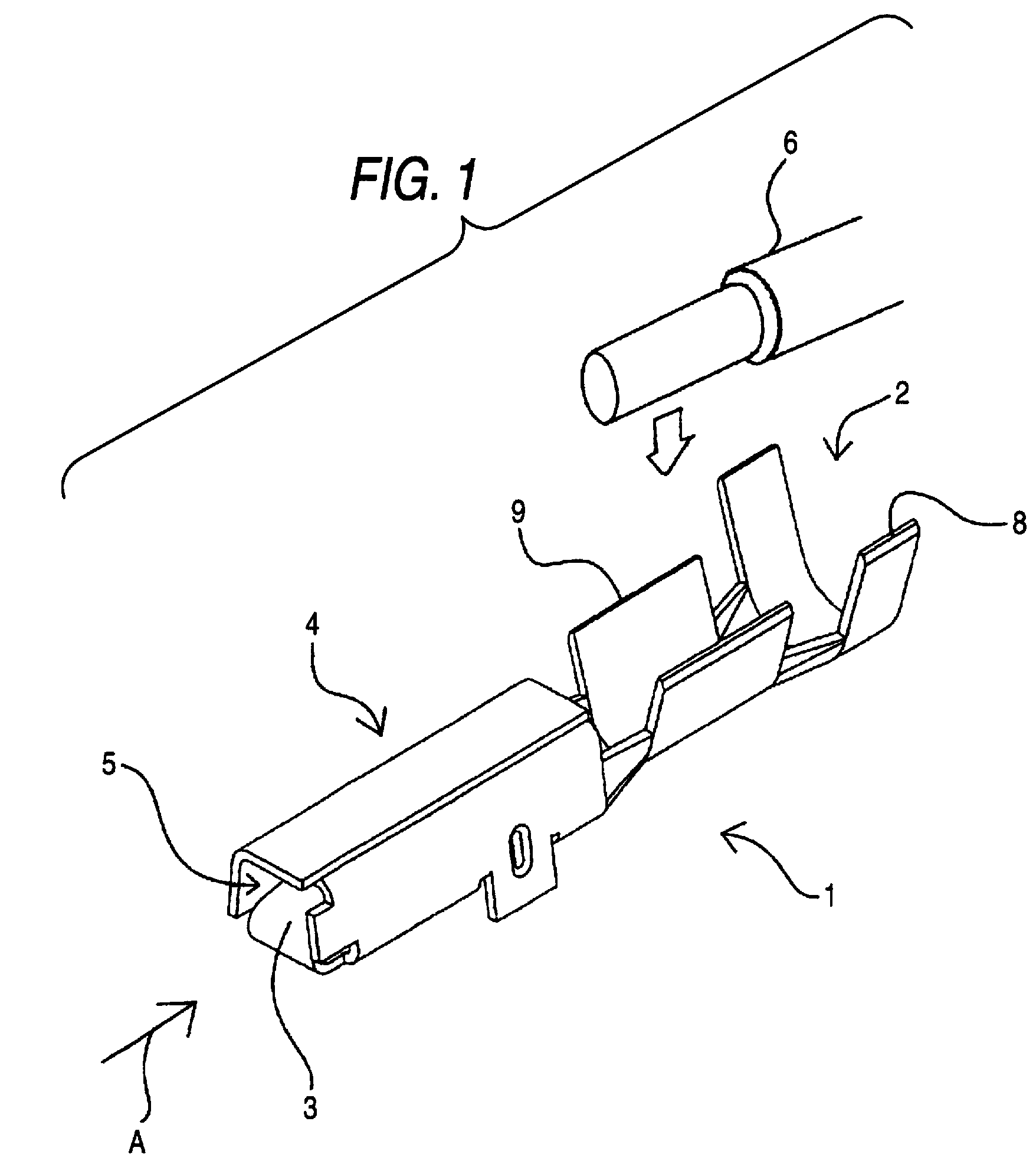
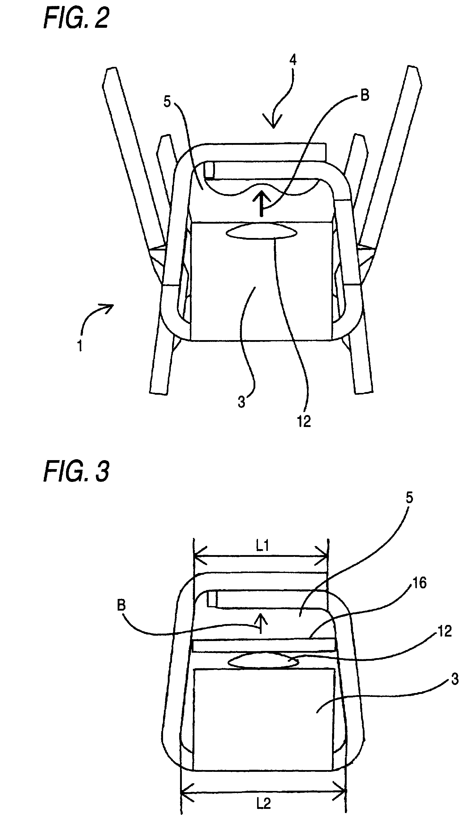
[0022]A preferred embodiment of the present invention will now be described with reference to the drawings. FIG. 1 is a perspective view showing the construction of a female terminal provided in accordance with the invention, FIG. 2 is a front-elevational view of the female terminal as seen in a direction of arrow A in FIG. 1, FIG. 3 shows a condition in which a male tab is inserted in the female terminal of FIG. 2, and FIG. 4 is a plan view showing a female terminal piece in its developed condition.

[0023]As shown in the drawings, the female terminal 1 of this embodiment includes a press-clamping portion 2, a spring portion 3, a tubular portion 4, and a space 5. The female terminal 1 is formed by blanking the female terminal piece (shown in its developed condition in FIG. 4) from a metal sheet and then by applying necessary processes (including a bending operation) to the female terminal piece.

[0024]The press-clamping portion 2 is adapted to be press-clamped to a wire 6 to be connec...


PUM


Abstract

A female terminal, includes: a tubular portion which is formed by bending a metal sheet into a tubular shape; a peripheral wall which has a trapezoidal cross section having a pair of opposed shorter and longer sides to form a space extending in an axial direction of the female terminal inside the tubular portion; and a spring portion for pressing a male terminal inserted in the space, in a direction toward the shorter side of the peripheral wall. A maximum width of the male terminal is longer than the shorter side and is shorter than the longer side.

Description

BACKGROUND OF THE INVENTION[0001]1. Technical Field[0002]This invention relates to a female terminal and a chain terminal thereof.[0003]2. Background Art[0004]Among connectors for interconnecting wire harnesses in an automobile, there is known the type of connector in which terminals made of metal are received within a receiving chamber formed in a housing made of a synthetic resin. In such a connector, when a housing having male terminals received therein is fitted to another housing having female terminals received therein, distal end portions (hereinafter referred to as “male tabs”) of the male terminals are inserted and received respectively in internal spaces of the female terminals. Thus, the male terminals are electrically connected to the female terminals, respectively.[0005]With respect to the structure of the female terminal into which the male tab is adapted to be inserted, for example, opposite side portions of a thin metal sheet are bent inwardly to form a pair of canti...

Claims


Application Information

Patent Timeline
Patent Type & Authority Patents(United States)
IPC IPC(8): H01R11/22H01R13/11
CPCH01R4/185H01R13/11H01R43/16
Inventor KUMAKURA, HIDETO
Owner YAZAKI CORP
Why Eureka
Try Eureka