Modular Energy Dissipation System

a technology of energy dissipation system and module, which is applied in the direction of shock absorption, elastic dampers, shockproofing, etc., can solve the problems of brittle behavior, adverse effects of welding junctions, and complicated manufacture, and achieve the effect of easy adaptability

Inactive Publication Date: 2011-02-10
UNIV DE GIRONA
View PDF9 Cites 7 Cited by
  • Summary
  • Abstract
  • Description
  • Claims
  • Application Information

AI Technical Summary

Benefits of technology

[0011]It is an object of the present invention to provide an energy dissipator not requiring stiffeners, the basic design of which being easily adaptable in order to be able to absorb different amounts of energy or to yield when subjected to forces of different magnitude. Another object is to allow the manufacture of the dissipator to be automated.
[0015]With the modular system comprising an elongated dissipator as described above, made in one piece with each module longitudinally integrated with the adjacent modules, said piece being relatively small (since each module does not have to be big), a bigger displacement is achieved with the same force because each module is subjected to the same force than the dissipator as a whole, but the displacement of the dissipator is the sum of the displacement of all modules, whereby the dissipator is capable of dissipating more energy. This is so because of the junction between the central strip of a module and the sidelong strips of an adjacent module, and vice versa, which allows a relative displacement in each module between its central strip and its sidelong strips.
[0023]Advantageously, the second connector comprises two Ω-shaped profiles joined through their flanges, and the first connector comprises two U-shaped profiles that are housed in corresponding axial spaces defined inside the Ω-shaped profiles of the second connector. In this way, when the dissipator yields the first connector can move inside the second connector.

Problems solved by technology

It is common to weld stiffeners to the dissipators in order to prevent web buckling from appearing, but welded junctions can have adverse effects, like brittle behavior, which are enhanced with thin webs.
The plates and the stiffeners are incorporated by welding, which makes its manufacture more complicate, and the plates increase the flexibility of the dissipator, which is not desirable.

Method used


Image

  • Modular Energy Dissipation System
  • Modular Energy Dissipation System
  • Modular Energy Dissipation System

Examples


Embodiment Construction

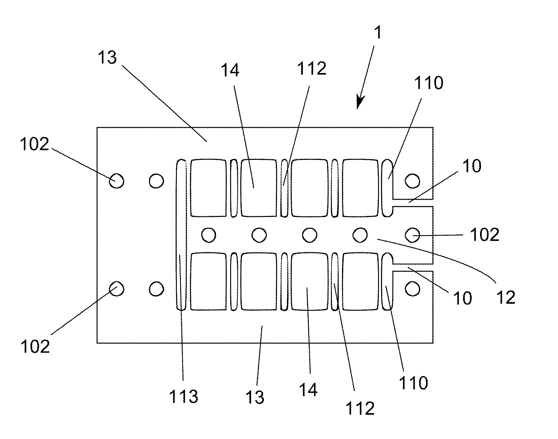
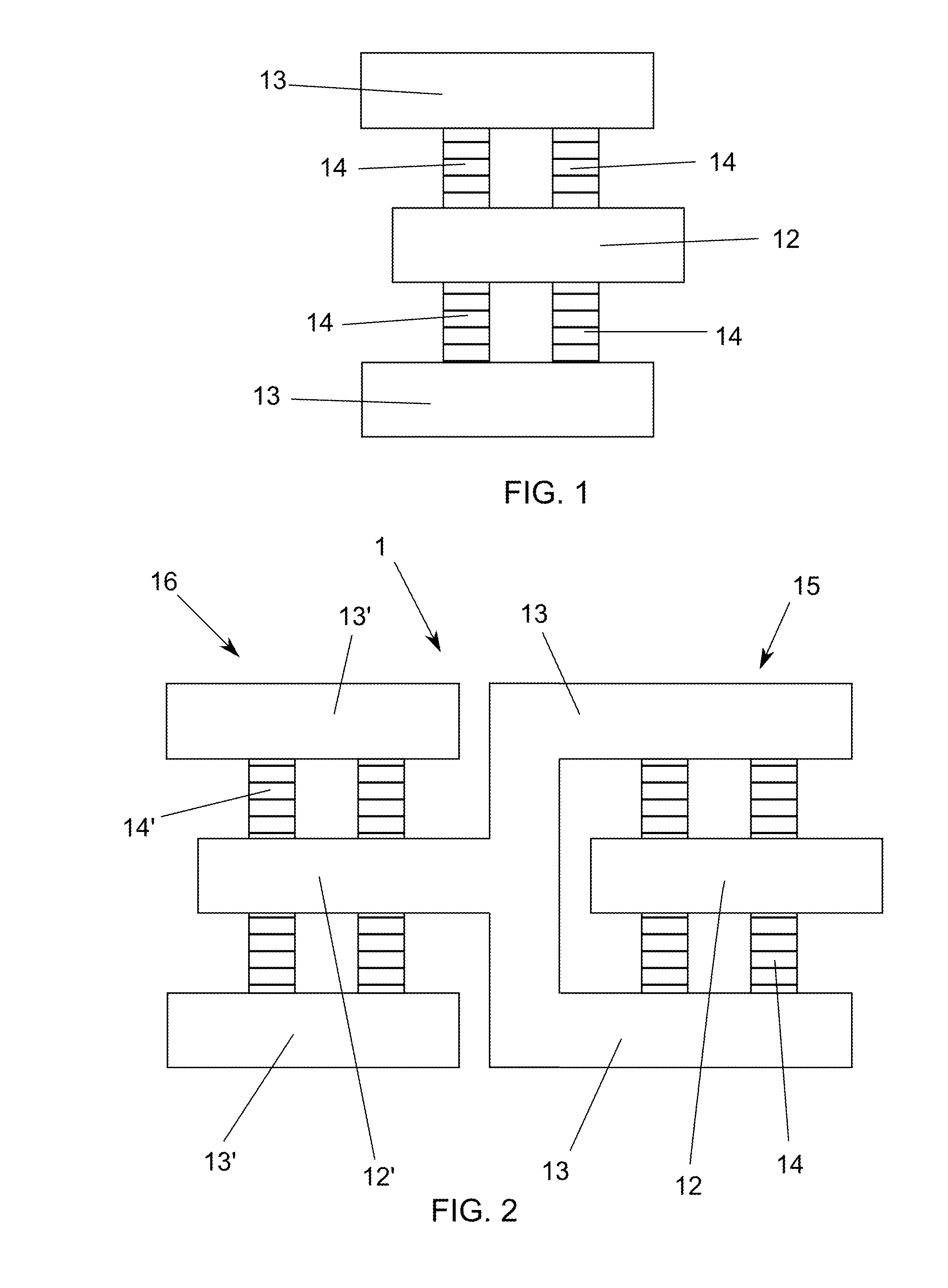
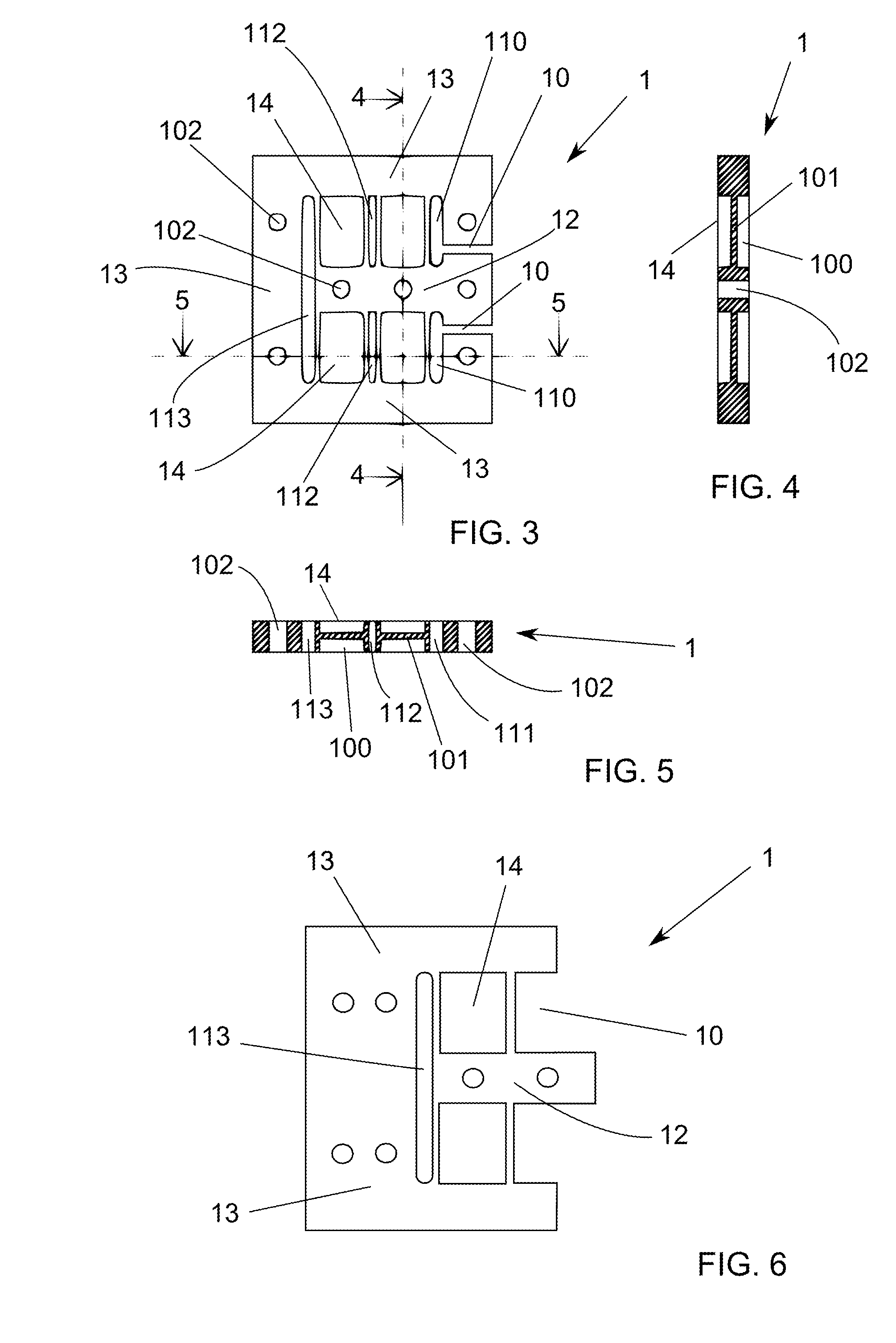
[0052]FIG. 1 schematically shows a basic dissipation module comprising a central strip 12 having a main direction substantially coincident with the linking direction to the two structural members, two sidelong strips 13 arranged along each side of (or above and below) the central strip 12 and having the same main direction thereof, and four yielding elements 14 symmetrically arranged between the central strip and the sidelong strips.

[0053]The yielding elements 14 are the basic elements which yield when the elements linking the dissipator to the structural members undergo a relative displacement important enough; this yielding provides the energy dissipation necessary to absorb the energy of the displacement. The yielding elements 14 yield mainly under shear stress or mainly under flexure stress; in the latter case they absorb bending moments and usually comprise some thin plates having a constant thickness and a variable cross-section (like for instance the dissipator known as ADAS)...


PUM


Abstract

Modular energy dissipation system for linking two structures in a linking direction, comprising a yielding energy dissipator (1) provided with at least two energy dissipation modules (15, 16) successively arranged along said linking direction, each module comprising a central strip (12; 12′), two sidelong strips (13; 13′) and a plurality of yielding elements (14; 14′) between the central strip and the sidelong strips, so that the central strip of a module located at one end of the dissipator is linked to one of the structures and the sidelong strips of this module are integrated with the central strip of the adjacent module, and the sidelong strips of the module located at the other end of the dissipator are linked to the other structure and the central strip of this module is integrated with the sidelong strips of the adjacent module.

Description

[0001]The present invention is related to a modular energy dissipation system for linking two structural members in a linking direction, comprising a yielding energy dissipator provided with a central strip, two sidelong strips and at least two yielding elements arranged at both sides of the central strip, between the latter and the two sidelong strips.[0002]Said structural members may be parts of just one building or of different buildings, or even whole buildings. A structural member is herein defined as an object presenting a resistant functionality against the loads (gravity, wind, seism, etc) acting on a building; structural members may include masonry and installations.BACKGROUND ART[0003]Various systems to reduce or avoid damage to a building or to several nearby buildings when subjected to a dynamic action (seism, wind, etc) are known. Their main aim is to control (reduce) the relative displacements taking place between structural members, which may belong to one building or...

Claims


Application Information

Patent Timeline
Patent Type & Authority Applications(United States)
IPC IPC(8): F16F7/12E04B1/98
CPCE04B1/98F16F7/12E04H9/022E04H9/0237E04H9/0215
Inventor CAHIS I CAROLA, FRANCESC XAVIER
Owner UNIV DE GIRONA
Why Eureka
Try Eureka