Energy storage device comprising a flywheel

Inactive Publication Date: 2011-02-10
ENERGIESTRO
View PDF24 Cites 25 Cited by
  • Summary
  • Abstract
  • Description
  • Claims
  • Application Information

AI Technical Summary

Benefits of technology

[0016]Therefore, the choice of materials for the kinetic plates and magnetic plates may be optimized, and further it is often possible to choose less costly materials as compared to the prior art without diminishing the mechanical and magnetic performance of the flywheel.
[0017]Further, the use of several magnetic plates enables to limit the magnetic

Problems solved by technology

However, this solution has at least two drawbacks.
Firstly, to limit the losses by Foucault currents, it is necessary to machine very thin and deep grooves on the magnetic pole areas, which requires special and costly machining techniques on such a big part.
Secondly, an unsatisfactory compromise is to be do

Method used


Image

  • Energy storage device comprising a flywheel
  • Energy storage device comprising a flywheel
  • Energy storage device comprising a flywheel

Examples


first embodiment

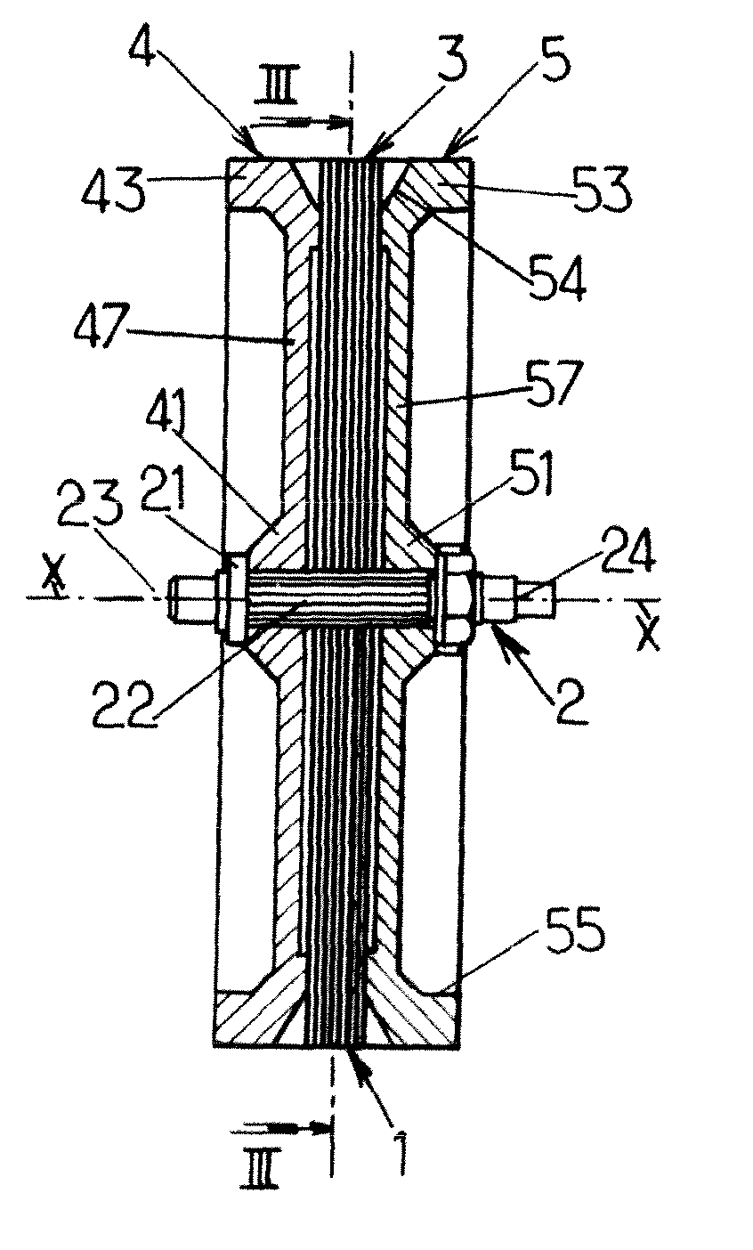
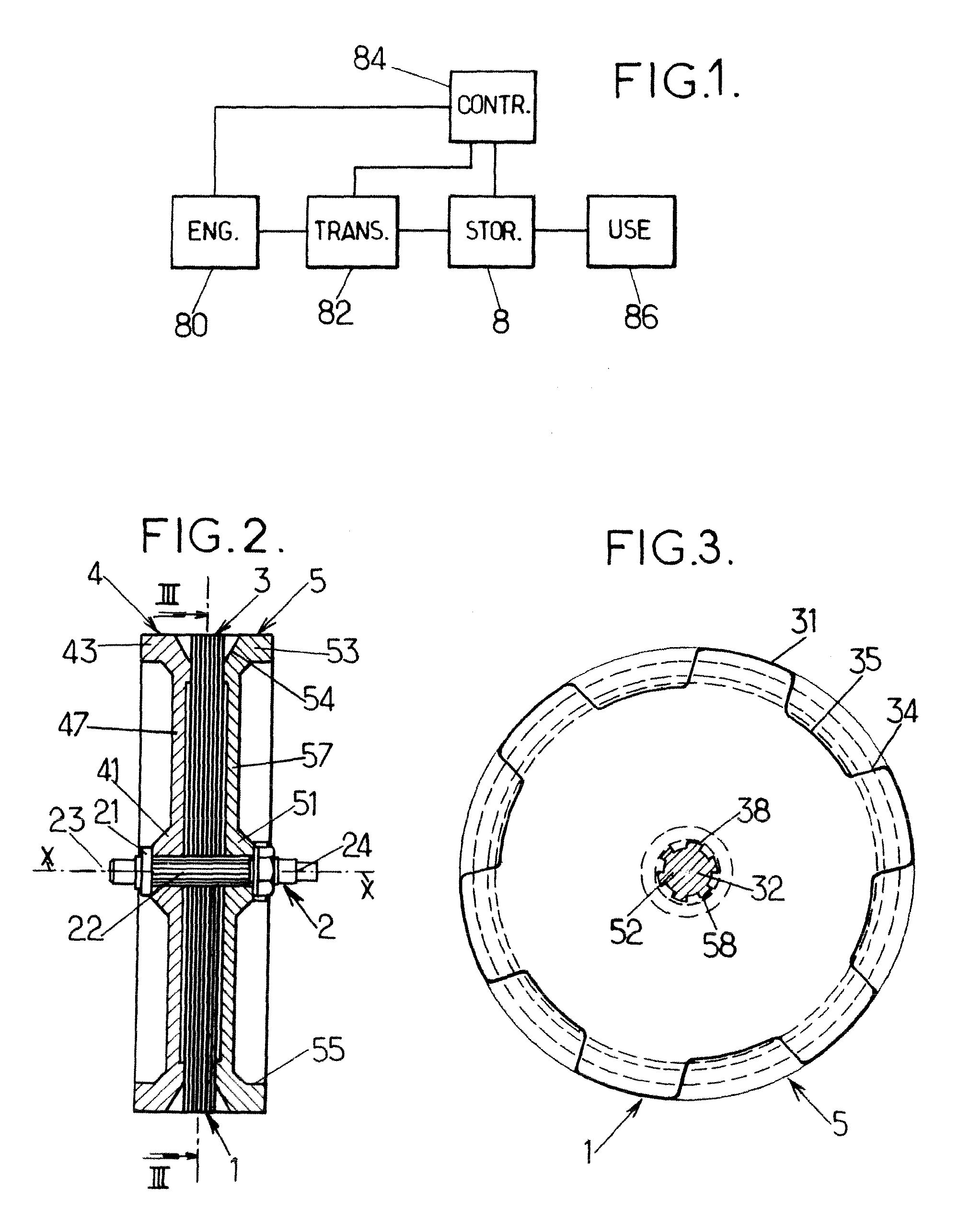
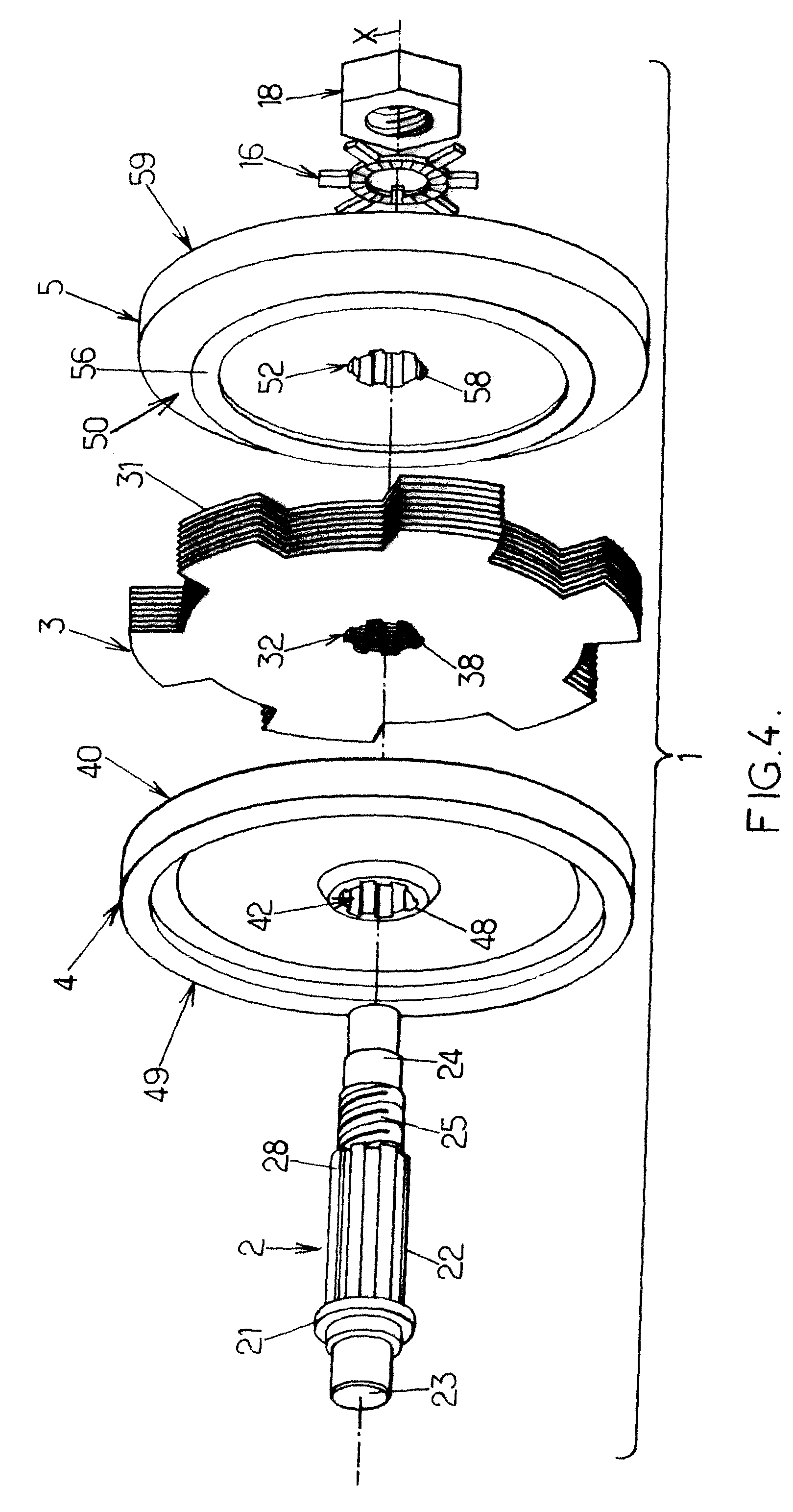
[0058]The energy storage device 8 comprises a flywheel 1 which is depicted on FIGS. 2, 3 and 4. This flywheel 1 rotates around an axis of rotation X, and comprises:[0059]a shaft 2[0060]a first kinetic plate 4[0061]a plurality of magnetic plates 3[0062]a second kinetic plate 5

[0063]The Shaft

[0064]The shaft 2 extends between a first and second ends and comprises:[0065]a first bearing 23 adjacent to the first end, adapted to be received in the inner ring of a first roller bearing 13, said first roller bearing 13 being received in the centre of a first housing side plate 63,[0066]a shoulder 21, adjacent to said first bearing 23, having a diameter greater than the diameter of the bore of the kinetic plates,[0067]a center portion 22, with a substantially constant section, receiving the kinetic plates 4,5 and the magnetic plates 3,[0068]a thread 25 to receive a lock washer 16 and a nut 18, said nut being rotationally secured by said lock washer,[0069]a second bearing 24 adjacent to the sec...

second embodiment

[0120]FIG. 7 shows a second embodiment of the energy storage device according to the invention. In this second embodiment of the invention, the energy storage device system is identical or similar to the one described in the first embodiment, thus it will not be described again. The housing 6 and the stator arrangement are also identical or similar to the ones described in the first embodiment, thus they will not be described again.

[0121]Only the flywheel assembly differs by the mechanical fitting on the shaft 2. The shaft comprises at least a longitudinal groove 91 extending along the rotation axis X and able to receive without clearance a locking pin 90. This locking pin 90 extends along the rotation axis X, has a smaller length than the shaft groove length, and has preferably a rectangular cross section partly received in the groove 91. When installed in the groove 91, the locking pin protrudes from the shaft periphery. The first kinetic plate 4 has a corresponding groove 94; the...


PUM


Abstract

Energy storage device comprising a flywheel a stator arrangement and a housing.
The flywheel, rotatably mounted around a rotation axis, comprises a shaft, a plurality of adjacent magnetic plates with magnetic poles, two kinetic plates, sandwiching the magnetic plates. The magnetic plates and kinetic plates are rotationally rigid with said shaft.
The stator arrangement comprises a plurality of induction coils cooperating with the magnetic poles.

Description

FIELD OF THE INVENTION[0001]The invention relates to an energy storage device comprising a flywheel.[0002]Such an energy storage device is for instance used in autonomous power generating systems.[0003]More precisely, the invention concerns an energy storage device comprising:[0004]a flywheel rotatably mounted around a rotation axis, said flywheel comprising a shaft and a plurality of magnetic poles,[0005]a stator arrangement, facing the magnetic poles of said flywheel, comprising a plurality of induction coils cooperating with said magnetic poles,[0006]a housing enclosing the flywheel and the stator arrangement.BACKGROUND OF THE INVENTION[0007]Patent application WO2005 / 043721 discloses an energy storage device comprising a flywheel able to store kinetic energy and a generator arrangement to provide electrical power from this kinetic energy. The flywheel is made of a single part from a ferromagnetic material.[0008]However, this solution has at least two drawbacks. Firstly, to limit ...

Claims


Application Information

Patent Timeline
IPC IPC(8): H02K7/02
CPCY02E60/16H02K7/025
Inventor GENNESSEAUX, ANDRE RENE GEORGES
Owner ENERGIESTRO
Why Eureka
Try Eureka