
Lifting hydraulic system and lifting machine with hydraulic system

A hydraulic system and mechanical technology, applied in the direction of lifting devices, etc., can solve the problems of low energy utilization rate and high fuel consumption, and achieve the effects of low cost, energy saving, reliability and accuracy

Active Publication Date: 2011-06-15
SANY MARINE HEAVY IND +1
View PDF4 Cites 21 Cited by
  • Summary
  • Abstract
  • Description
  • Claims
  • Application Information

AI Technical Summary

Problems solved by technology

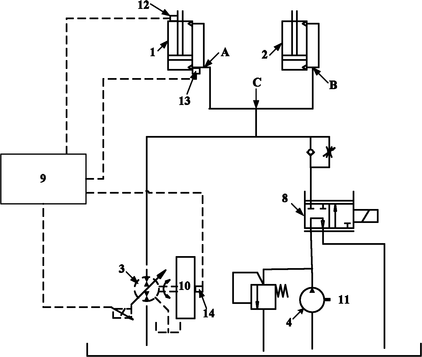
[0006] The present invention aims to provide a lifting hydraulic system and a lifting machine with the lifting hydraulic system, the lifting hydraulic system can solve the technical problems of low energy utilization rate and high fuel consumption of the hydraulic system used for lifting operations

Method used


Image

  • Lifting hydraulic system and lifting machine with hydraulic system
  • Lifting hydraulic system and lifting machine with hydraulic system
  • Lifting hydraulic system and lifting machine with hydraulic system

Examples


Embodiment Construction

[0024] The embodiments of the present invention will be described in detail below with reference to the accompanying drawings, but the present invention can be implemented in many different ways defined and covered by the claims.

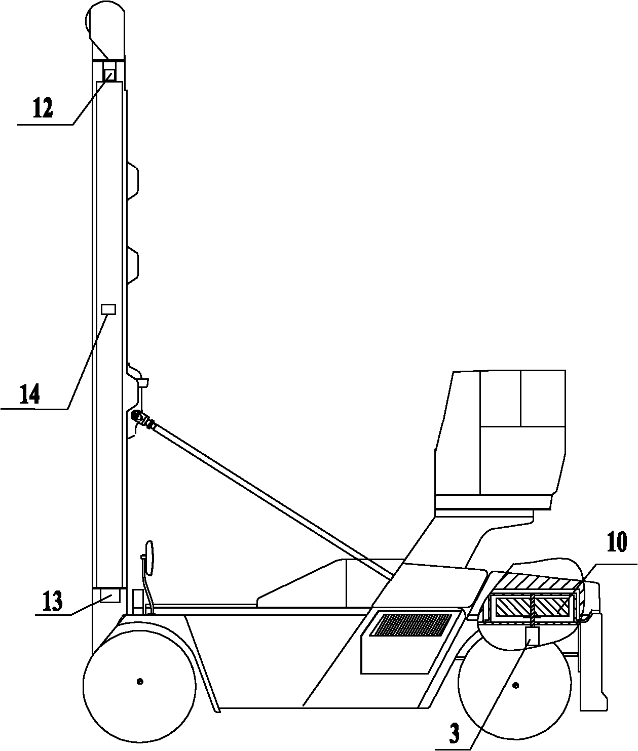
[0025] The present invention provides a lifting hydraulic system and a lifting mechanism with the lifting hydraulic system. As a preferred embodiment, the lifting mechanism can be a port machine, such as a stacker. Combine below figure 1 with figure 2 , the structure of the lifting hydraulic system provided by the present invention and the working process of the forklift equipped with the lifting hydraulic system will be described.

[0026] In order to recover the potential energy when the spreader of the stacker falls, the lifting hydraulic system provided by the present invention includes a hydraulic cylinder that drives the lift to lift, that is, a lifting cylinder, a variable hydraulic pump / motor 3, a flywheel 10, and a fuel tank. In order to...


PUM


Abstract

The invention provides a lifting hydraulic system and a lifting machine with the hydraulic system. The lifting hydraulic system comprises an oil tank, lifting oil cylinders and a volume adjustable hydraulic pump / motor, wherein an oil inlet pipeline and an oil discharge pipeline of each lifting oil cylinder are connected to a node; and the volume adjustable hydraulic pump / motor comprises an oil passing cavity communicated between the node and the oil tank, a rotor arranged in the oil passing cavity, a transmission shaft with a first end connected with the rotor, and a flywheel connected to thesecond end of the transmission shaft. When the lifting oil cylinders discharge oil, the volume adjustable hydraulic pump / motor works as a hydraulic motor and drives the flywheel to store energy; and when the lifting oil cylinders are fed with the oil, the volume adjustable hydraulic pump / motor works as a hydraulic pump driven by the flywheel to feed the hydraulic oil into the lifting oil cylinders. The lifting hydraulic system provided by the invention can save a great amount of energy in frequent container stacking operation; the flywheel can be used as a counterweight so as to bring convenience to layout; moreover, the flywheel reduces the impact of the hydraulic oil onto each part of the system at the same time of saving the energy, and ensures the running stability of the lifting hydraulic system.

Description

technical field [0001] The present invention relates to a hydraulic system, in particular, to a lifting hydraulic system. In addition, the present invention also relates to a lifting machine comprising the above-mentioned lifting hydraulic system. Background technique [0002] With the increasingly serious problems of energy shortage and environmental pollution, improving the energy-saving and environmental protection performance of construction machinery and reducing exhaust emissions have become one of the important directions of construction machinery research. [0003] The mobile port machinery used for lifting usually uses a hydraulic system to realize the lifting of the spreader. During the process of hoisting or stacking goods, these hydraulic systems need to be driven by engines with sufficient power, which in turn consume a lot of fuel. This makes mobile port machinery based on these hydraulic systems a source of energy consumption and pollution in port operations....

Claims


Application Information

Patent Timeline
Patent Type & Authority Applications(China)
IPC IPC(8): B66F9/22B66F9/07
Inventor 梁爽廖荣华李翠英
Owner SANY MARINE HEAVY IND
Learn More