Display device
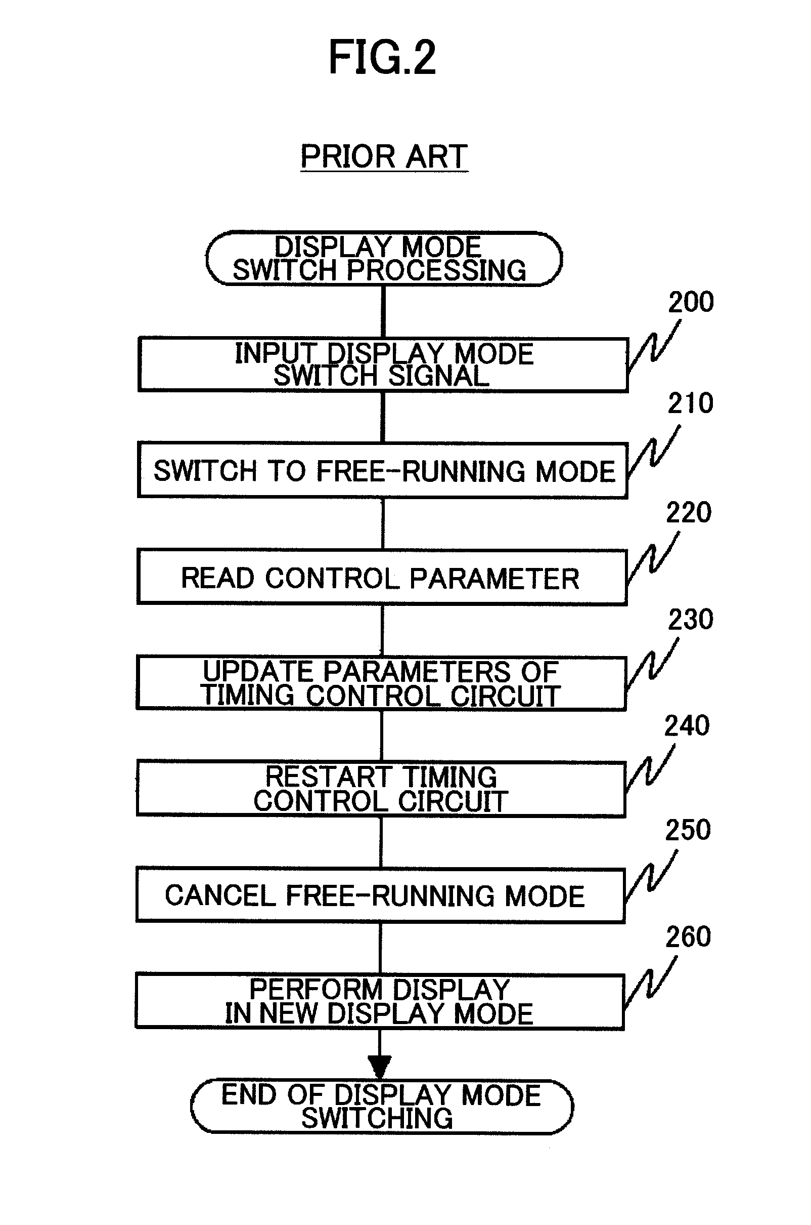
a display device and display screen technology, applied in the field of display devices, can solve the problems of revealing at all the factor of image quality degradation occurring in the switching of frame frequency, and achieve the effect of preventing image quality degradation, such as frame drops and flicker
- Summary
- Abstract
- Description
- Claims
- Application Information
AI Technical Summary
Benefits of technology
Problems solved by technology
Method used
Image
Examples
first embodiment
Overall Configuration
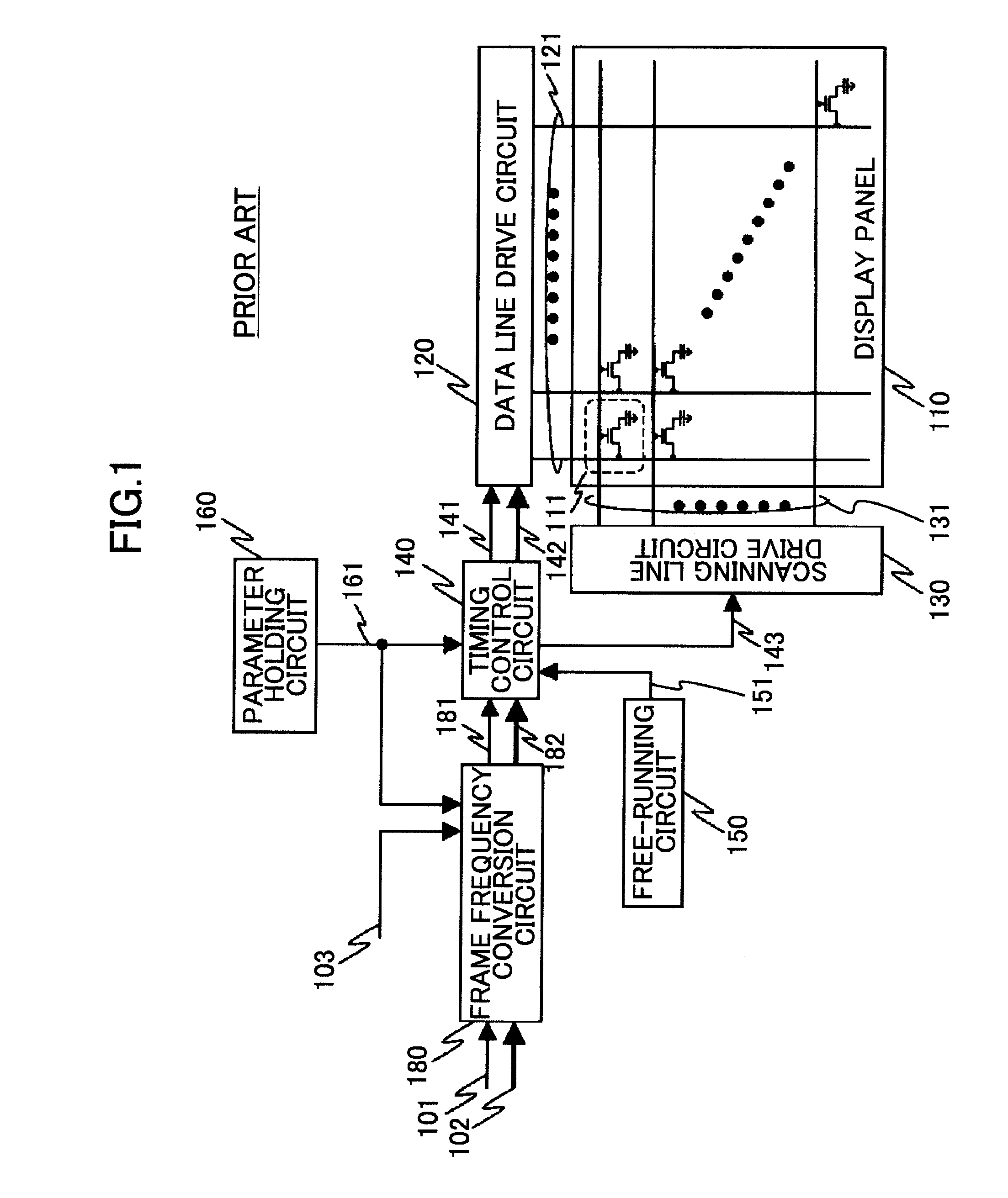
[0038]FIG. 6 is a diagram illustrating a schematic configuration of a display device according to a first embodiment of the present invention. Referring to FIG. 6, an overall configuration of the display device according to the first embodiment is described below. It should be noted that the description is directed to a case where the present invention is applied to a liquid crystal display panel as a display panel illustrated in FIG. 6. Other display panels are applicable as long as a corresponding display device includes a scanning line drive circuit and a data line drive circuit, such as an organic electroluminescence (EL) panel, a liquid crystal on silicon (LCOS) display, a plasma display panel, a field emission display, and electronic paper.
[0039]The display device according to the first embodiment illustrated in FIG. 6 is provided with at least two display modes using different frame frequencies, for example, 60 Hz and 120 Hz, and is provided with a functi...
second embodiment
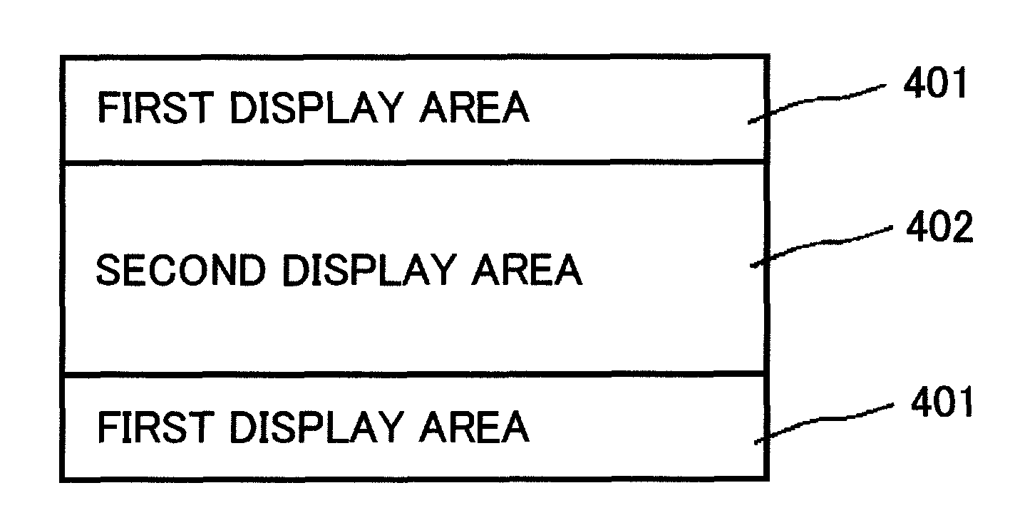
[0121]FIGS. 16(a) to 16(e) are diagrams illustrating scanning operations of scanning lines in a third display mode performed in a display device according to a second embodiment of the present invention. FIG. 16(a) illustrates a scanning operation of the scanning lines in a first display mode, FIGS. 16(b) to 16(d) each illustrate the scanning operation of the scanning lines in the third display mode (during display mode transition), and FIG. 16(e) illustrates a scanning operation of the scanning lines in a second display mode. It should be noted that the display device according to the second embodiment has the same configuration as the display device according to the first embodiment except for a display method for the second display area in the third display mode. Therefore, in the following, detailed description is given of the scanning operation of the scanning lines in the third display mode. In FIGS. 16(a) to 16(e), the horizontal axis represents time and the vertical axis rep...
third embodiment
[0131]FIGS. 17(a) to 17(e) are diagrams illustrating scanning operations of scanning lines in a third display mode performed in a display device according to a third embodiment of the present invention. FIG. 17(a) illustrates a scanning operation of the scanning lines in a first display mode, FIGS. 17(b) to 17(d) each illustrate the scanning operation of the scanning lines in the third display mode (during display mode transition), and FIG. 17(e) illustrates a scanning operation of the scanning lines in a second display mode. It should be noted that the display device according to the third embodiment has the same configuration as the display device according to the first embodiment except for a display method for the second display area in the third display mode. Therefore, in the following, detailed description is given as to the scanning operation of the scanning lines in the third display mode. In FIGS. 17(a) to 17(e), the horizontal axis represents time and the vertical axis re...
PUM
 Abstract
Description
Claims
Application Information
 - R&D
- Intellectual Property
- Life Sciences
- Materials
- Tech Scout
- Unparalleled Data Quality
- Higher Quality Content
- 60% Fewer Hallucinations
Browse by: Latest US Patents, China's latest patents, Technical Efficacy Thesaurus, Application Domain, Technology Topic, Popular Technical Reports.
© 2025 PatSnap. All rights reserved.Legal|Privacy policy|Modern Slavery Act Transparency Statement|Sitemap|About US| Contact US: help@patsnap.com


