Check patentability & draft patents in minutes with Patsnap Eureka AI!

Electrical penetrator assembly

a technology of penetrator and assembly, which is applied in the direction of sealing/packing, coupling device connection, and wellbore/well accessories, etc., can solve the problems of extreme environment for the connector or penetrator, the inability of the connection or penetrator to be isolated from the pumping pressure, and the inability to manufacture and use the penetrator after use. , to achieve the effect of reducing stress

Active Publication Date: 2011-02-10
TELEDYNE INSTR INC
View PDF77 Cites 12 Cited by
  • Summary
  • Abstract
  • Description
  • Claims
  • Application Information

AI Technical Summary

Benefits of technology

[0010]In another embodiment, an electrical penetrator assembly comprises a ceramic housing having a through bore with opposite first and second ends, a rigid conductor extending into the first end of the bore and terminating short of the second end, and a flexible conductor secured to the inner end of the conductor and extending out of the second end of the bore, with a suitable seal arrangement between the conductor and bore at one end, and between the flexible conductor and bore at the other end of the assembly. In this arrangement, the flexible conductor moves to compensate for different rates of thermal expansion and contraction of the rigid conductor, ceramic housing, and seals, reducing stress between the sealing sleeves and ceramic or insulating housing.

Problems solved by technology

In an ESP application, the connection or penetrator cannot be isolated from the pumping pressure for practical reasons.
This creates an extreme environment for the connector or penetrator in terms of pressure, temperature, and high voltage.
This causes problems in manufacture and in subsequent use of the penetrator, due to the different coefficients of expansion of the different materials used in the penetrator assembly.
Once the penetrator assembly is allowed to cool, the different rates of shrinkage of the different material parts causes stress on the ceramic housing material, brittle bonds, or both, and may lead to failure of the seal.
Additionally, most existing penetrators are designed for high pressure on one side only, and application of pressure on the other side may cause additional stress on the seal arrangement and the ceramic housing.

Method used


Image

  • Electrical penetrator assembly
  • Electrical penetrator assembly
  • Electrical penetrator assembly

Examples


Embodiment Construction

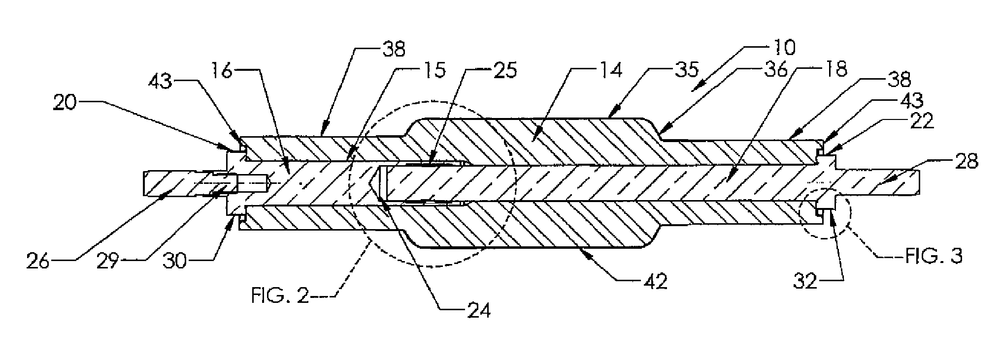
[0025]Certain embodiments as disclosed herein provide for an electrical penetrator assembly suitable for use in high pressure applications, such as in providing power for subsea equipment.

[0026]After reading this description it will become apparent to one skilled in the art how to implement the invention in various alternative embodiments and alternative applications. However, although various embodiments of the present invention will be described herein, it is understood that these embodiments are presented by way of example only, and not limitation. As such, this detailed description of various alternative embodiments should not be construed to limit the scope or breadth of the present invention.

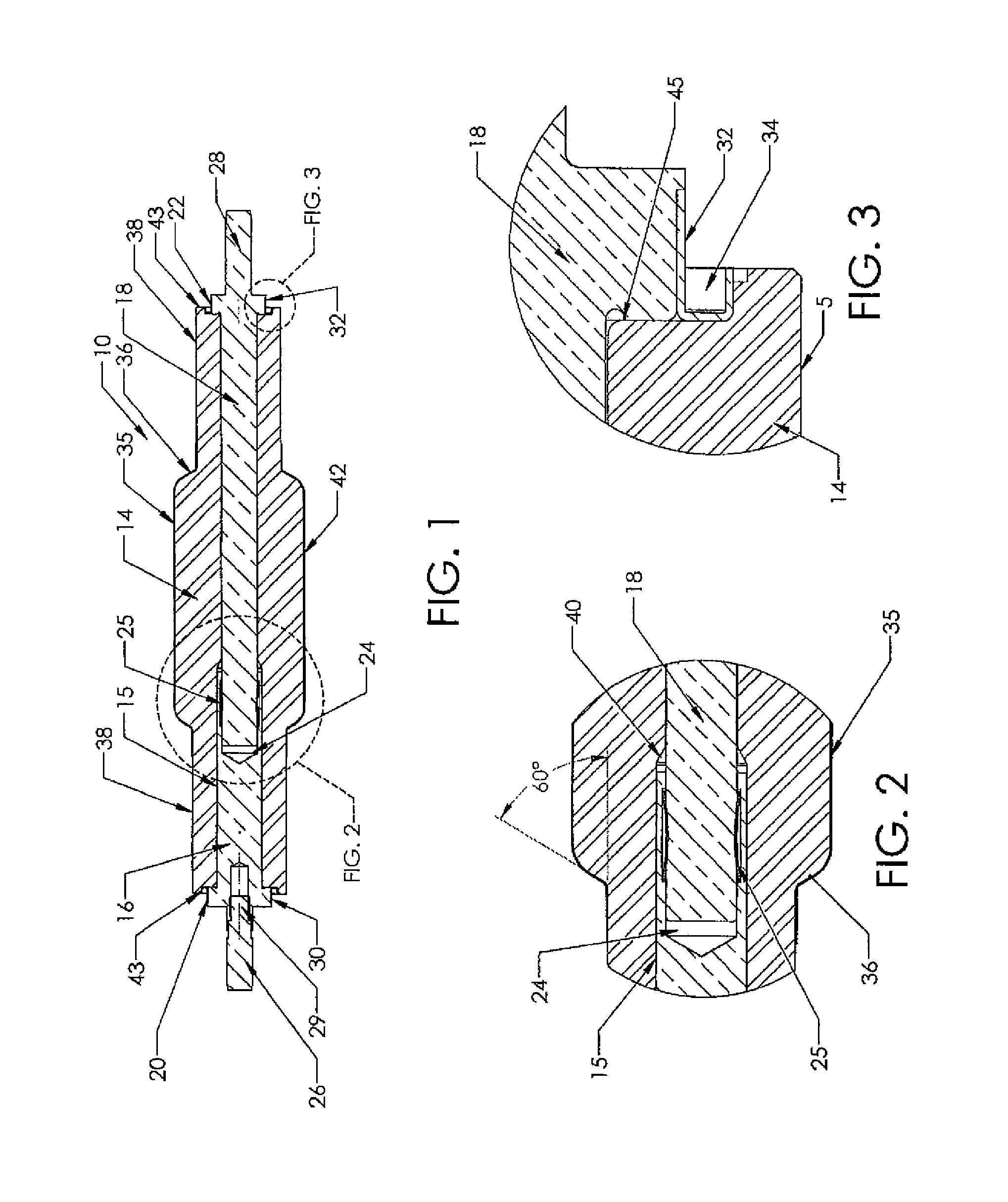
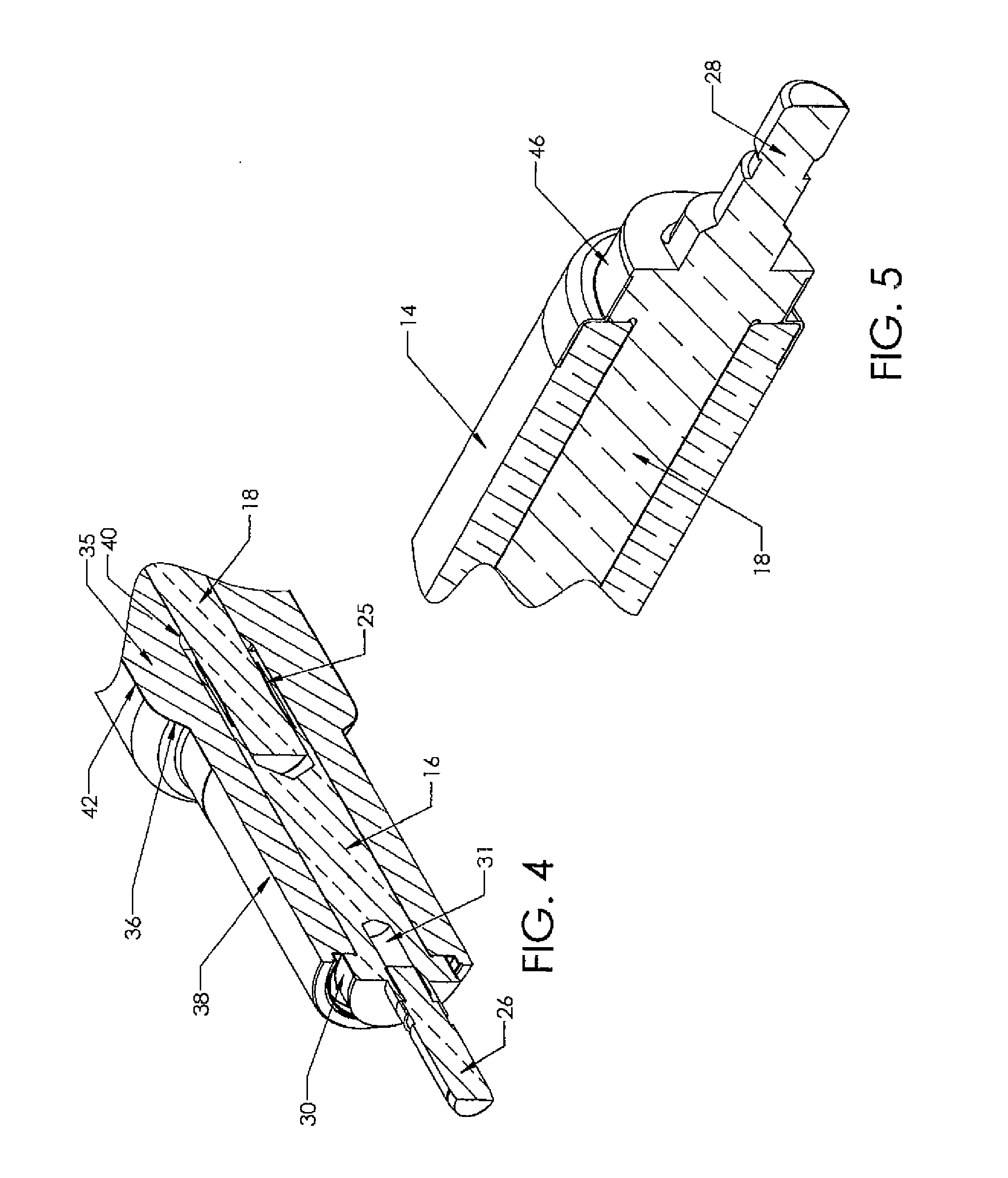
[0027]FIGS. 1 to 4 illustrate a first embodiment of an electrical penetrator pin assembly or subassembly 10, while FIG. 6 illustrates the assembly 10 mounted in an outer penetrator housing 12 for extending through a wall or bulkhead of a subsea vessel or container. The pin subassembly 10 i...


PUM


Abstract

An electrical penetrator assembly has a ceramic housing with a through bore, a first electrical conductor extending through a first end of the bore and terminating short of a second end of the bore and having an outer end engageable with a first cable, and a second electrical conductor extending through a second end of the bore and terminating short of the first end of the bore, the second conductor having an outer end engageable with a second cable. The conductors are in electrical communication at their inner ends and at least one of the conductors is movable relative to the other conductor to accommodate expansion and contraction as a result of temperature variations, and first and second seals extend between respective ends of the ceramic housing and the first and second conductor, respectively.

Description

RELATED APPLICATION[0001]The present application claims the benefit of co-pending U.S. provisional pat. App. Ser. No. 61 / 231,521, filed Aug. 5, 2009, the contents of which are incorporated herein by reference in their entirety.BACKGROUND[0002]1. Field of the Invention[0003]The present invention relates generally to electrical penetrator assemblies for feed through of electrical power through the wall of a pressurized vessel or the like, and is particularly concerned with an electrical penetrator assembly for subsea use.[0004]2. Related Art[0005]Electrical penetrators are used to power subsea electric submersible pump (ESP) equipment and the like which pump hydrocarbons in oil well installations, and also in other applications such as high pressure downhole electrical penetrations and other penetrations to provide power to various types of subsea equipment. The penetrator extends through the wall or bulkhead of the vessel in which the equipment is located, and is normally connected t...

Claims


Application Information

Patent Timeline
Patent Type & Authority Applications(United States)
IPC IPC(8): H01R41/00H01R13/40H01R13/52
CPCH02G3/22H01R13/187H02G9/02E21B33/0385
Inventor SIVIK, GREGORYFOLEY, THOMASJAZOWSKI, ROY
Owner TELEDYNE INSTR INC
Features
  • R&D
  • Intellectual Property
  • Life Sciences
  • Materials
  • Tech Scout
  • Unparalleled Data Quality
  • Higher Quality Content
  • 60% Fewer Hallucinations
Learn More