Golf ball

a golf ball and dimple technology, applied in the field of golf balls, can solve problems such as disturbance of air flow

Inactive Publication Date: 2011-02-10
SUMITOMO RUBBER IND LTD
View PDF4 Cites 30 Cited by
  • Summary
  • Abstract
  • Description
  • Claims
  • Application Information

AI Technical Summary

Benefits of technology

[0028]Preferably, the sum (Ps+Pp) is equal to or less than 1000 mm. Preferably, an absolute value of a difference (Ps−Pp) between the peak value Ps and the peak value Pp is equal to or less than 250 mm.
[0029]Preferably, each of the order Fs and the order Fp, which are obtained by the steps (1) to (18), is equal to or greater than 20 and equal to or less than 40. An absolute value of a difference (Fs−Fp) between the order Fs and the order Fp is equal to or less than 10.
[0030]Each of a northern hemisphere and a southern hemisphere of the surface of the golf ball has a pole vicinity region and an equator vicinity region. A dimple pattern of the pole vicinity region includes a plurality of units that are rotationally symmetrical to each other about the pole. A dimple pattern of the equator vicinity region includes a plurality of units that are rotationally symmetrical to each other about the pole. Preferably, the number Np of the units of the pole vicinity region is different from the number Ne of the units of the equator vicinity region. Preferably, the number Np is equal to or greater than 3 and equal to or less than 6. Preferably, the number Ne is equal to or greater than 3 and equal to or less than 6. Preferably, one of

Problems solved by technology

This difference d

Method used


Image

  • Golf ball
  • Golf ball
  • Golf ball

Examples


example 1

[0123]A rubber composition was obtained by kneading 100 parts by weight of a polybutadiene (trade name “BR-730”, available from JSR Corporation), 30 parts by weight of zinc diacrylate, 6 parts by weight of zinc oxide, 10 parts by weight of barium sulfate, 0.5 parts by weight of diphenyl disulfide, and 0.5 parts by weight of dicumyl peroxide. This rubber composition was placed into a mold including upper and lower mold halves each having a hemispherical cavity, and heated at 170° C. for 18 minutes to obtain a core with a diameter of 39.7 mm. On the other hand, a resin composition was obtained by kneading 50 parts by weight of an ionomer resin (trade name “Himilan 1605”, available from Du Pont-MITSUI POLYCHEMICALS Co., LTD.), 50 parts by weight of another ionomer resin (trade name “Himilan 1706”, available from Du Pont-MITSUI POLYCHEMICALS Co., LTD.), and 3 parts by weight of titanium dioxide. The above core was placed into a final mold having numerous pimples on its inside face, foll...

example 2

[0124]A golf ball of Example 2 was obtained in a similar manner as Example 1, except the final mold was changed. This golf ball has a dimple pattern shown in FIGS. 15 and 16. In this dimple pattern, each equator vicinity region has six units, and each pole vicinity region has three units. The latitude of each boundary line is 23°. The detailed specifications of the dimples are shown in the following Table 1. The peak values and the orders are shown in the following Table 3.

example 3

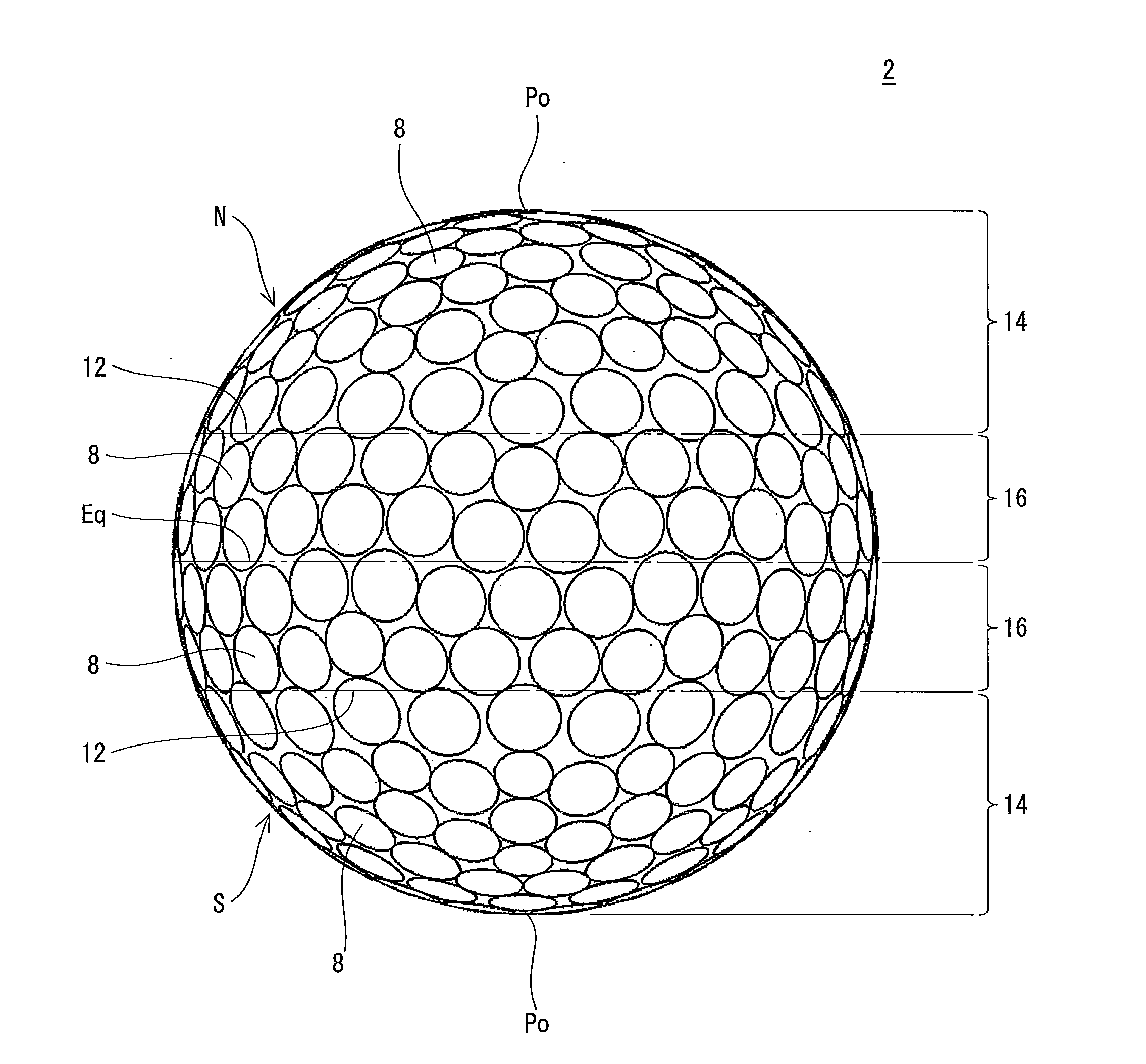
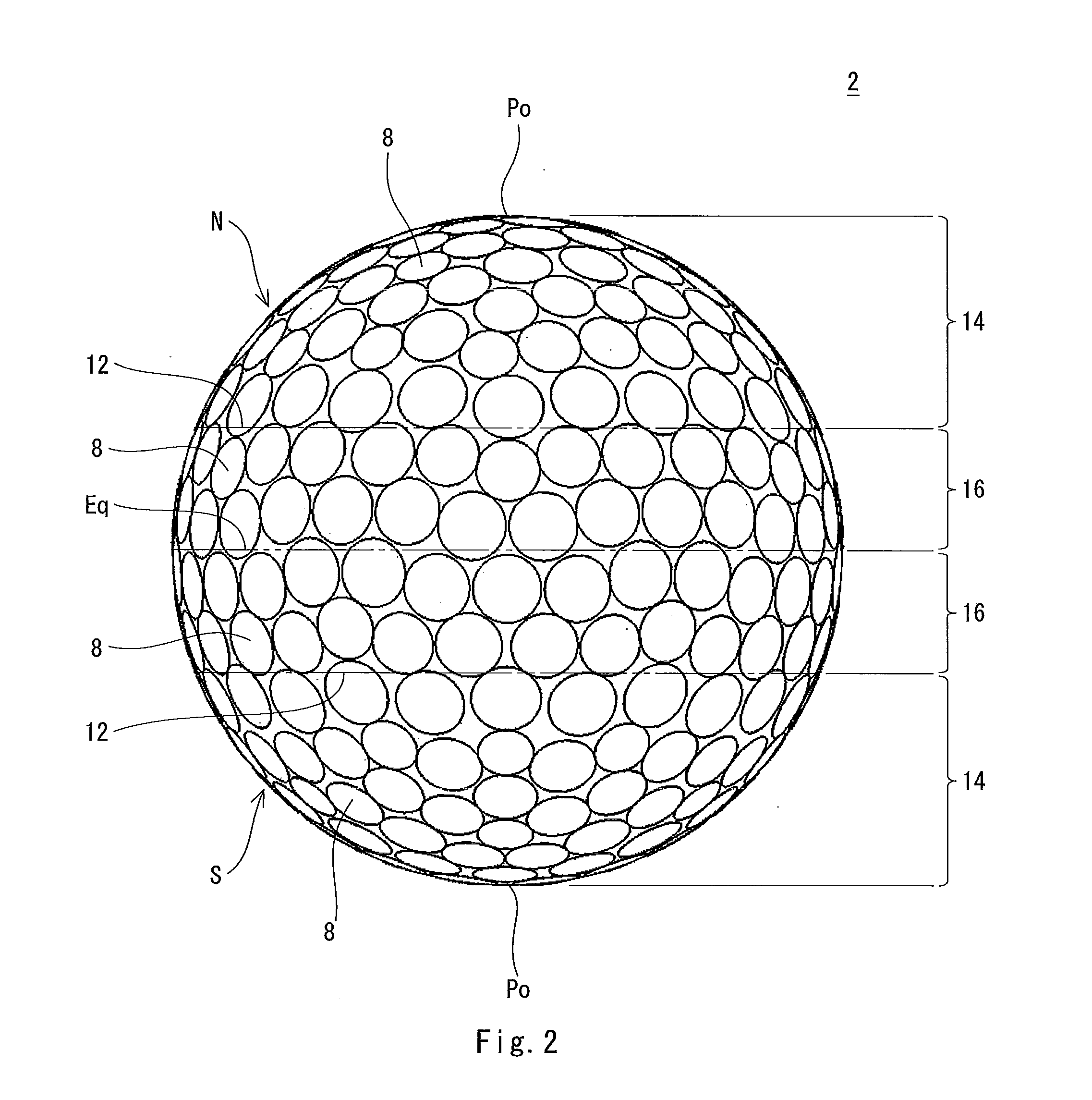
[0125]A golf ball of Example 3 was obtained in a similar manner as Example 1, except the final mold was changed. This golf ball has the dimple pattern shown in FIGS. 2 and 3. In this dimple pattern, each equator vicinity region has six units, and each pole vicinity region has three units. The latitude of each boundary line is 23°. The detailed specifications of the dimples are shown in the following Table 1. The peak values and the orders are shown in the following Table 3.


PUM


Abstract

The golf ball 2 has a northern hemisphere N and a southern hemisphere S. The northern hemisphere N is adjacent to the southern hemisphere S across an equatorial line Eq. Each of the northern hemisphere N and the southern hemisphere S has a pole vicinity region 14 and an equator vicinity region 16. Each of the pole vicinity region 14 and the equator vicinity region 16 has a large number of dimples. The dimple pattern of the pole vicinity region 14 includes three units that are rotationally symmetrical to each other about a pole Po. The dimple pattern of the equator vicinity region 16 includes six units that are rotationally symmetrical to each other about the pole Po. The sum (Ps+Pp) of a peak value Ps and a peak value Pp of the golf ball 2 is equal to or greater than 600 mm.

Description

[0001]This application claims priority on Patent Application No. 2009-182032 filed in JAPAN on Aug. 5, 2009. The entire contents of this Japanese Patent Application are hereby incorporated by reference.BACKGROUND OF THE INVENTION[0002]1. Field of the Invention[0003]The present invention relates to golf balls. Specifically, the present invention relates to improvement of dimples of golf balls.[0004]2. Description of the Related Art[0005]Golf balls have a large number of dimples on the surface thereof. The dimples disturb the air flow around the golf ball during flight to cause turbulent flow separation. By causing the turbulent flow separation, separation points of the air from the golf ball shift backwards leading to a reduction of drag. The turbulent flow separation promotes the displacement between the separation point on the upper side and the separation point on the lower side of the golf ball, which results from the backspin, thereby enhancing the lift force that acts upon the ...

Claims


Application Information

Patent Timeline
IPC IPC(8): A63B37/14
CPCA63B37/0006A63B37/0021A63B37/002A63B37/0019A63B37/00065
Inventor SAJIMA, TAKAHIRONAKAMURA, HIROTAKAKIM, HYOUNGCHOL
Owner SUMITOMO RUBBER IND LTD
Why Eureka
Try Eureka