Graphical user interface device

a user interface and graphical technology, applied in the direction of instruments, testing/monitoring control systems, information technology support systems, etc., can solve the problems of increasing the number of monitoring and control data items, complicated functions, etc., and achieve the effect of reducing the time required for the operator to check a target data item

Active Publication Date: 2011-02-10
MITSUBISHI ELECTRIC CORP
View PDF34 Cites 58 Cited by
  • Summary
  • Abstract
  • Description
  • Claims
  • Application Information

AI Technical Summary

Benefits of technology

[0009]According to the subject of the present invention, the guidance information provided by the system includes the device ID and the operation ID of the subsequent operation, and thus it is possible to avoid the operation of returning once to an initial screen for checking other data. As a result, the effect that the time required for the operator to check a target data item can be reduced is attained.
[0010]Referring now to the attached drawings, the embodiments of the subject of the present invention will be described in detail in conjunction with effects and advantages thereof

Problems solved by technology

Nowadays, demands for functions become complicated in a monitoring and control system of a power plant and, for example, the function of handling an accident as well as the function of preventing an erroneous operation are added to a conventional plant monitoring and controlling function.
The number of monitoring and control data items tend to increase as a power plant and a plant monitoring and control system become complicated.

Method used


Image

  • Graphical user interface device
  • Graphical user interface device
  • Graphical user interface device

Examples


first embodiment

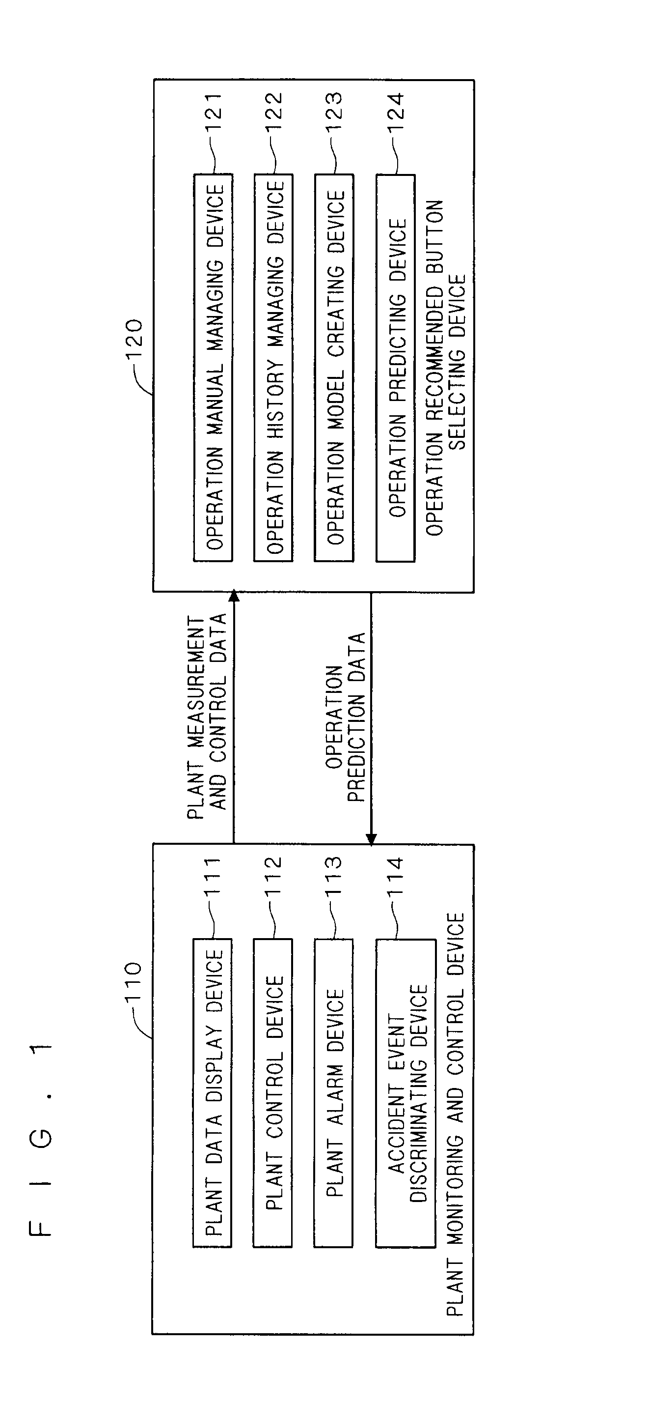
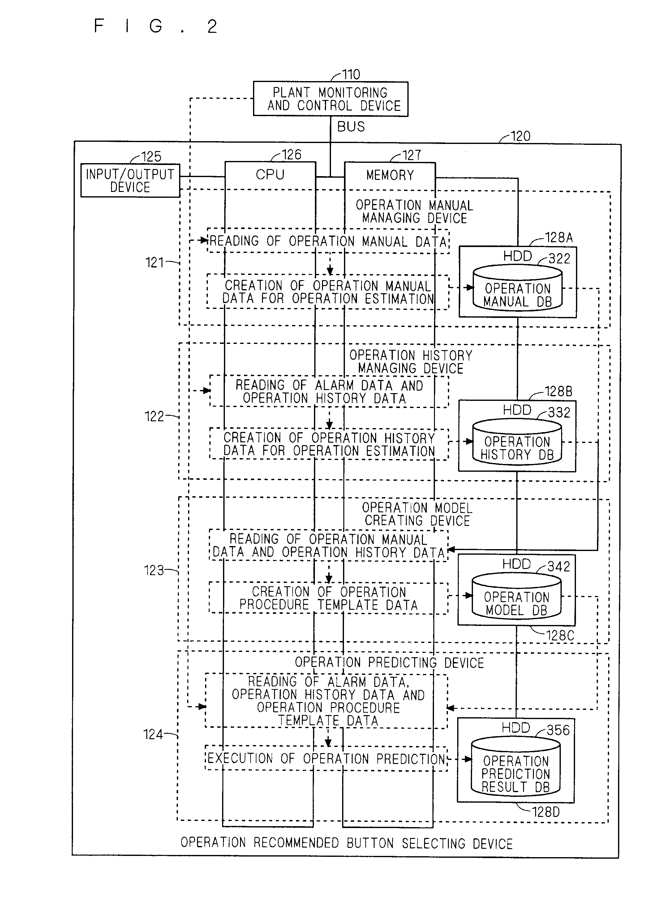
[0020]FIG. 1 is a block diagram showing the configuration of a plant monitoring control device according to the present embodiment. The plant monitoring and control device has the configuration in which an operation recommended button selecting device 120 is added to a conventional plant monitoring and control device 110.

[0021]The plant monitoring and control device 110 includes, as components thereof, (1) a plant data display device 111 that visualizes plant information by a graphical user interface and transmits it to an operator, (2) a plant control device 112 that controls a plant by the graphical user interface, (3) a plant alarm device 113 that compares a value of data measured in the plant with a reference value set in advance in a system to discriminate between normality and abnormality of the measured data value, (4) an accident event discriminating device 114 that discriminates a degree of importance of an alarm in a case where multiple pieces of abnormal data have been fo...

second embodiment

[0042]FIG. 7 is a flowchart showing an internal operation of the operation recommended button selecting device 120 included in the graphical user interface device according to the present embodiment. Note that the configuration and operation of the plant monitoring and control device are similar to those of the first embodiment.

[0043]The device 120 of FIG. 7 is the device that finds, in a case where specific operation details are not defined and prepared in the operation manual, such as a normal monitoring task, the regularity of the pieces of operation history data in during normal case that are stored in the operation history DB 332 when the operation of the same procedure is repeatedly performed.

[0044]Pattern operation creating means 343 of the operation model creating device 123 periodically searches the data of the operation history DB 332 and as a consequence, in a case where, for example, multiple spots of the same pattern arrangement are found in the screen number list, regi...

third embodiment

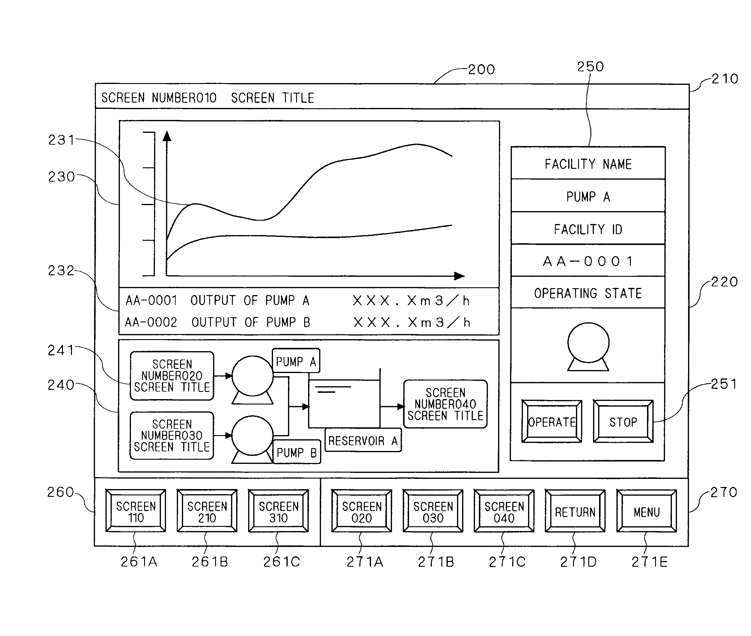
[0048]FIG. 8 is a diagram showing an example of the screen configuration of the plant monitoring and control system, which is a target of the present invention. Here, a menu screen 510 is set as the hierarchically top screen. Respective screens have reciprocal links in a hierarchical manner, and the screen configuration is designed so as to reach an appropriate monitoring screen by following the links between the screens. Provided in the upper part of the hierarchical structure are macro information screens 520A to 520C regarding the entire plant and, in a case where the operator checks detailed data relating to the macro information A screen 520A, it is required to transit to any of a detailed information A-1 screen 530A to a detailed information A-3 screen 530C that are linked to the macro information A screen 520A. Note that screen hierarchy may be classified in the units of facilities, units of functions or the like. Any number of screens are set to have the depth of the hierarc...


PUM


Abstract

In a large-scale plant such as a power plant, a graphical user interface device displays a target data display screen without increasing a load of searching a screen or a load of grasping a screen transition link. An operation model-creating device reads operation manual data for operation estimation and operation history data from an operation manual managing device and an operation history managing device to create a number of pieces of manual procedure template data for each accident type. An operation predicting device selects the operation procedure template data having same conditions of immediately preceding operation history data obtained from the plant monitoring and control device to predict the next operation estimated to be performed by an operator from the selected operation procedure template data. The plant monitoring and control device displays a system recommended operation button on a monitoring screen thereof based on data of the predicted results.

Description

TECHNICAL FIELD[0001]The present invention relates to a graphical user interface device in a monitoring and control system for monitoring and controlling a large-scale plant such as a power plant.BACKGROUND ART[0002]Nowadays, demands for functions become complicated in a monitoring and control system of a power plant and, for example, the function of handling an accident as well as the function of preventing an erroneous operation are added to a conventional plant monitoring and controlling function. The monitoring and control system is provided with a graphical user interface device for alleviating an operational load on an operator that increases as the system becomes complicated as described above. The graphical user interface device has the function of notifying an operator of an operating state of a power plant in an intuitively easy-to-understand manner, using display of digital values, display of a graph, colors, display of a pattern and the like. In addition, the graphical u...

Claims


Application Information

Patent Timeline
Patent Type & Authority Applications(United States)
IPC IPC(8): G06F3/048
CPCG05B23/0272Y04S10/52
Inventor UENO, YOHEIOI, TADASHIKAWAGISHI, MOTOHIKO
Owner MITSUBISHI ELECTRIC CORP
Why Eureka
Try Eureka