
Dryer for material to be dried

a drying machine and material technology, applied in drying, furnace types, light and heating equipment, etc., can solve the problems of drying machine type inability to clean inside using water, dryer type subject to particularly high thermal expansion, and dryer type subject to a particularly high thermal expansion

Active Publication Date: 2011-02-17
BINDER
View PDF14 Cites 4 Cited by
  • Summary
  • Abstract
  • Description
  • Claims
  • Application Information

AI Technical Summary

Problems solved by technology

However, this has the disadvantage that the inner trough is subjected to particularly high thermal expansion under the prevailing interior temperatures and strongly distorts thereby with an advanced operating period, and can even break at individual points.
Furthermore, the built-in internal insulation in vibrating dryer types is destroyed

Method used


Image

  • Dryer for material to be dried
  • Dryer for material to be dried
  • Dryer for material to be dried

Examples


Embodiment Construction

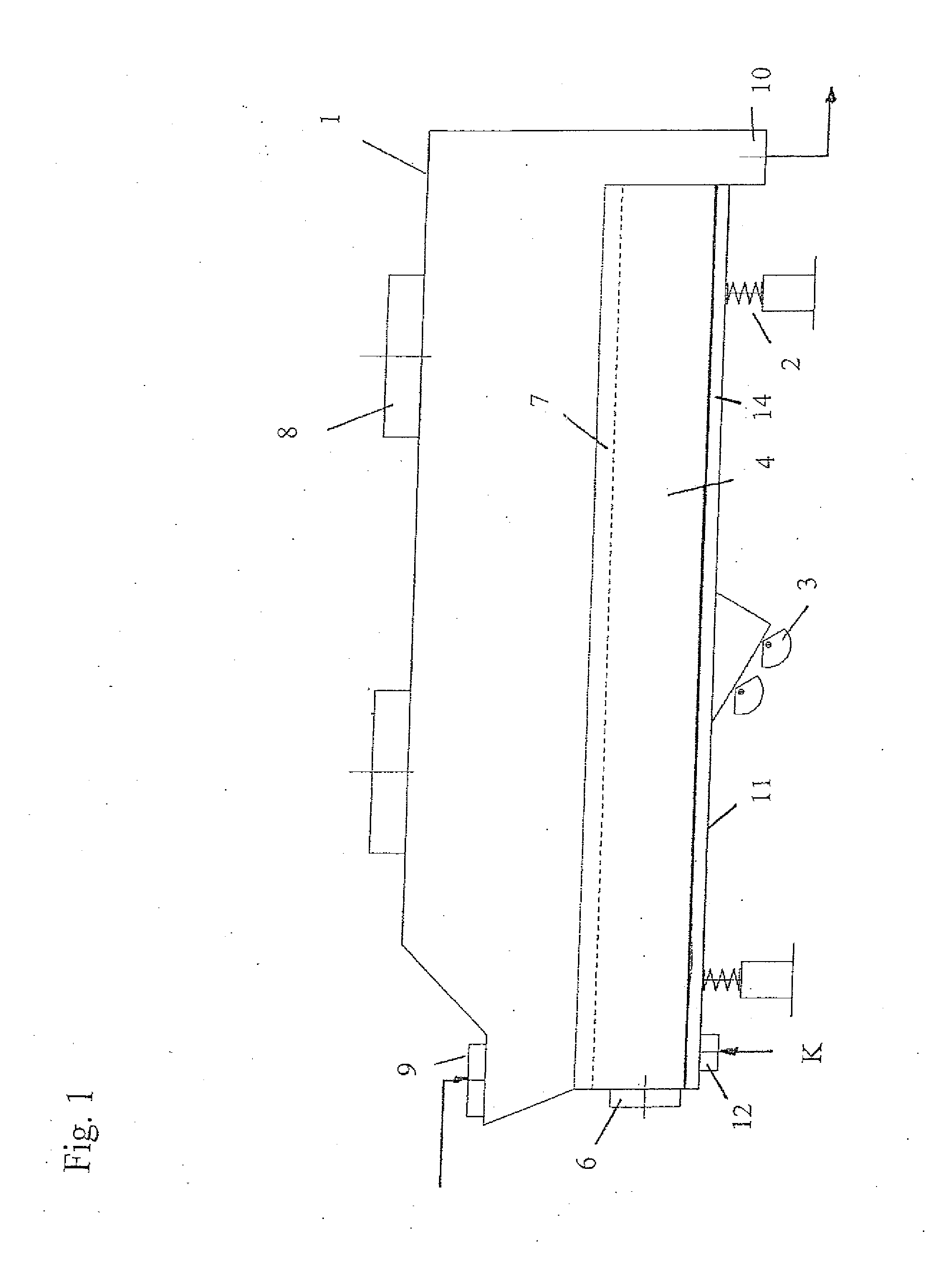
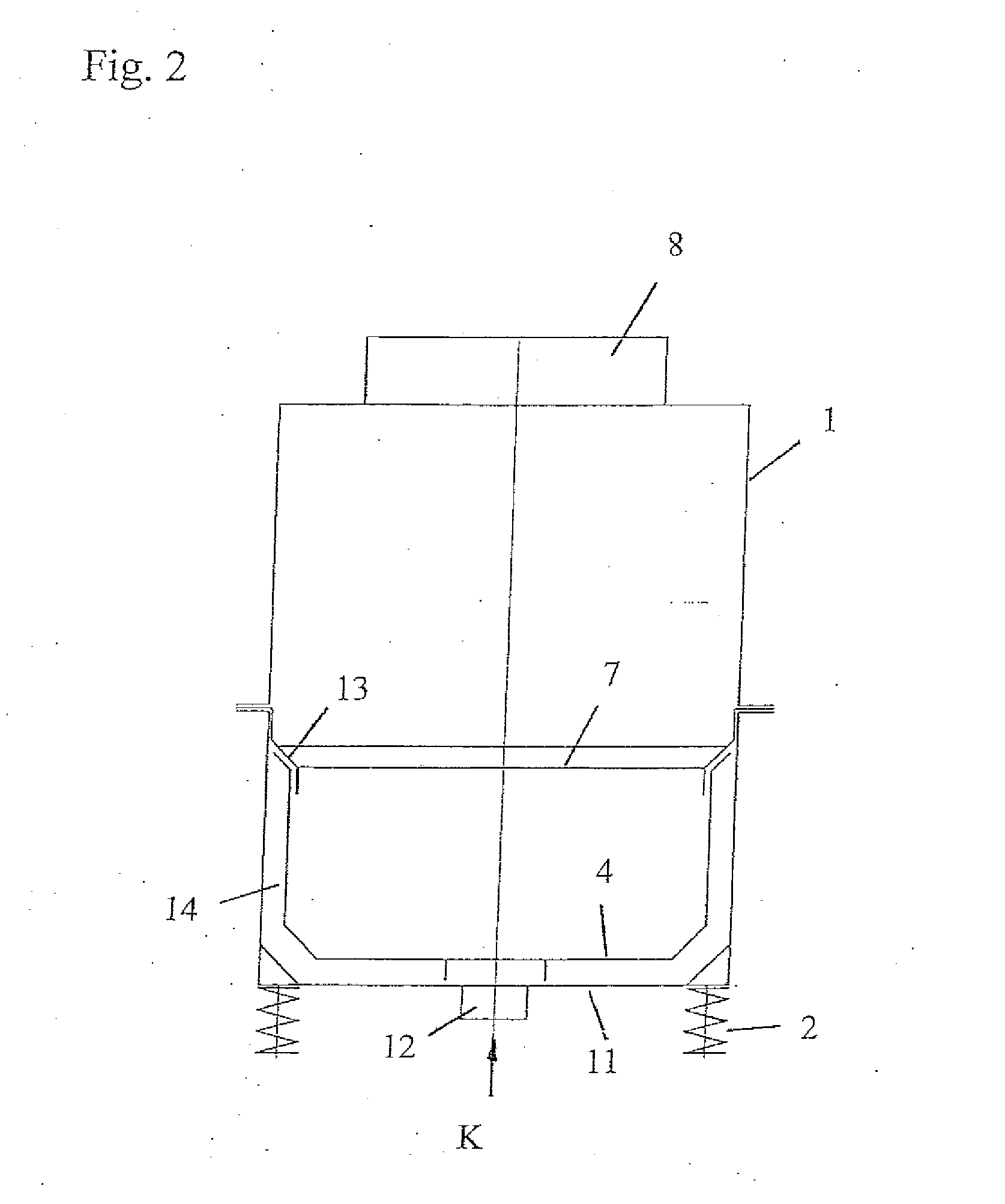
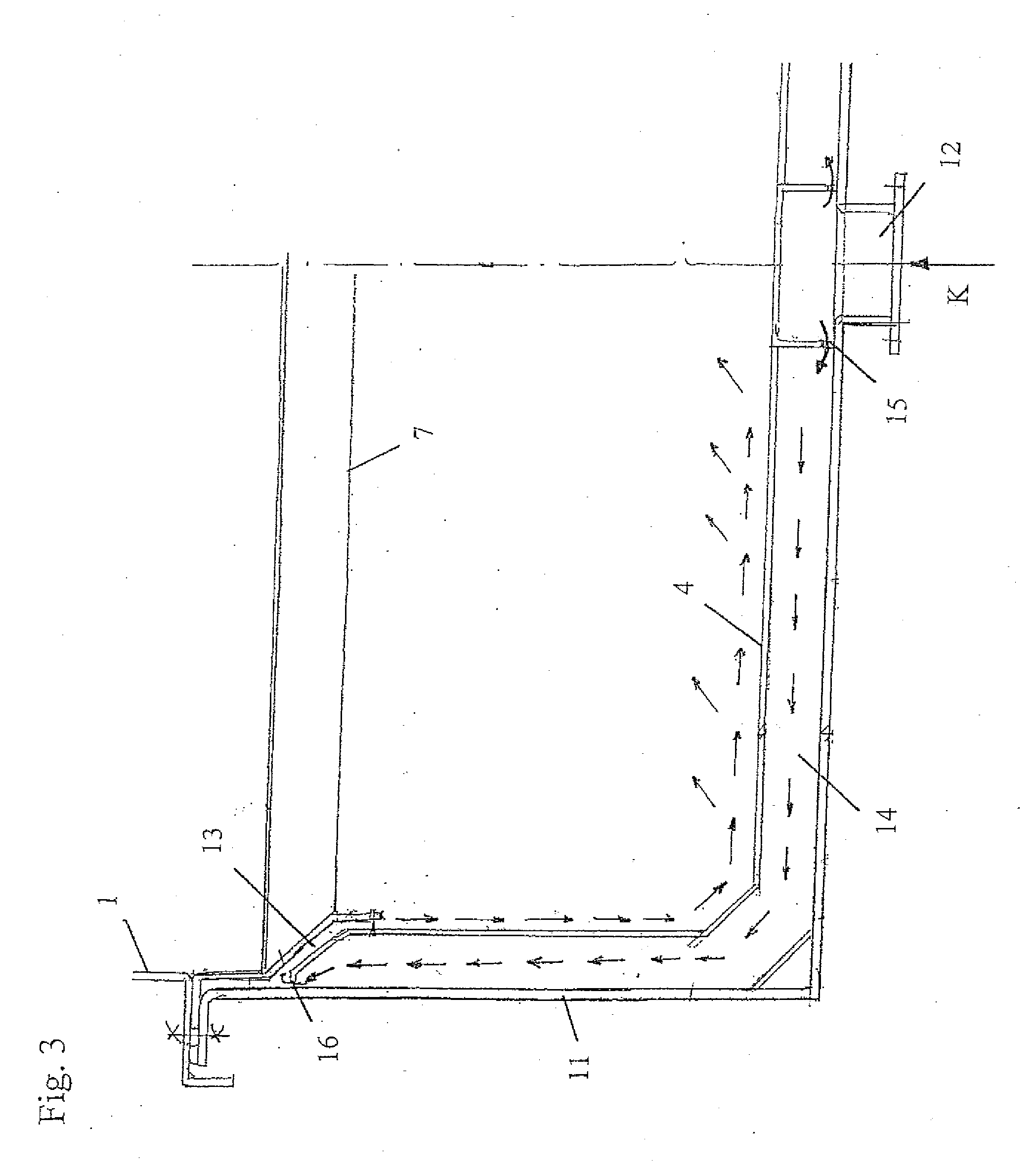
[0024]FIG. 1 shows an embodiment of a dryer according to the invention based on a vibrating fluid bed dryer comprising a casing 1, which is vibrated through spring assemblies 2 and a relevant vibration drive 3. Said dryer is provided with a feeding point 9 for the material to be dried T as well as a delivery point 10 for the material to be dried T, wherein the material to be dried T passes through a drying region between the feeding point 9 and the delivery point 10.

[0025]Furthermore, drying air that was heated by means of a hot gas generator 5 (see FIG. 4) is supplied to the dryer through the air supply opening 6 of an air supply channel 4. Generally, the air supply channel 4 is located thereby in the lower regions of the dryer, and is bounded towards the top by an inflow floor 7, such as a perforated floor plate, on which the material to be dried T is transported. The air supply channel 4 is also often designated as “inner trough” due to its trough-shaped design, and is connected ...


PUM


Abstract

A dryer for material to be dried (T), wherein an air supply channel (4) for supplying a drying gas to the drying region is provided, and at least one exhaust-gas opening (8) is provided for removing the drying gas, wherein the air supply channel (4) is surrounded at a distance by an outer wall (11), which has at least one supply opening (12) and at least one removal opening (13) for the cooling medium (K), wherein between the at least one supply opening (12) and the at least one removal opening (13) a flow section (14) for the cooling medium (K) is formed between the outer wall (11) and the air supply channel (4). According to the invention, the at least one removal opening (13) is configured as a through-opening in the air supply channel (4), which connects the region bounded by the outer wall (11) to the interior of the air supply channel (4), wherein the at least one through-opening (13) is arranged in the upper regions of the air supply channel (4) and is configured in such a way as to make it possible for the cooling medium (K) to flow downwards along the inner side of the air supply channel (4).

Description

SCOPE OF THE INVENTION[0001]The invention relates to a dryer for material to be dried comprising a feeding point for the material to be dried, a drying region, as well as a delivery point for the material to be dried, wherein an air supply channel for supplying a drying gas, preferably drying air, to the drying region is provided, as well as at least one exhaust-gas opening is provided for removing the drying gas after passing through the drying region, wherein the air supply channel is surrounded at least in sections at a distance by an outer wall, which has at least one supply opening for supplying a cooling medium as well as at least one removal opening for the cooling medium, wherein between the at least one supply opening and the at least one removal opening a flow section for the cooling medium is formed between the outer wall and the air supply channel according to the introductory clause of claim 1.STATE OF THE ART[0002]Dryers of this type are used in the minerals industry, ...

Claims


Application Information

Patent Timeline
IPC IPC(8): F26B3/00
CPCF26B3/0923F26B25/10F26B17/26
Inventor ANIBAS, FRANZ
Owner BINDER
Features
  • Generate Ideas
  • Intellectual Property
  • Life Sciences
  • Materials
  • Tech Scout
  • Unparalleled Data Quality
  • Higher Quality Content
  • 60% Fewer Hallucinations
Learn More