
Archery lighted release aid apparatus

a technology of lighted release and aid, which is applied in the direction of firing/trigger mechanism, compressed gas guns, white arms/cold weapons, etc., can solve the problems of difficulty in attaching a release aid to the bowstring, arrows may fly in undesirable angled flight paths, and archers may miss the ideal shot at the intended target, etc., to achieve easy activation, low operating current, and long operational life

Inactive Publication Date: 2011-02-17
FREITAG WILLIAM C +1
View PDF6 Cites 19 Cited by
  • Summary
  • Abstract
  • Description
  • Claims
  • Application Information

AI Technical Summary

Benefits of technology

[0018]Still another object of the invention is to provide a lighted release aid apparatus that preferably utilizes a light source that permits directional illumination, as well as one which operates with very low operating current so as to ensure long operational life.
[0019]Yet still another object of the invention is to provide an apparatus that is easy to activate so it does not alert the potential target that an arrow is about to be shot.

Problems solved by technology

Archers hunting in low light conditions, for example, in the early morning, early evening, or in the deep woods, often have difficulty attaching a release aid to the bowstring or loop and / or setting the arrow to the nocking position of the bowstring.
Without the use of a release aid, the arrow may fly in an undesirable angled flight path caused by the unequal pressure on the bowstring of the finger / fingers and thumb at the time of release.
Delay in attaching the release aid to the bowstring or loop due to poor visibility can cause the archer to miss the ideal shot at the intended target.
A delayed shot at the target under non-ideal conditions may cause a complete miss or a wounding of the target instead of a kill.
While one could practice to hopefully make the attachment process faster and more reliable, trying to attach a release aid in dark or dusky conditions is not a sure thing even with practice.
In any of the prior art, leaving the light on can compromise the presence of the hunter and therefore cause the prey to flee.

Method used


Image

  • Archery lighted release aid apparatus
  • Archery lighted release aid apparatus
  • Archery lighted release aid apparatus

Examples


Embodiment Construction

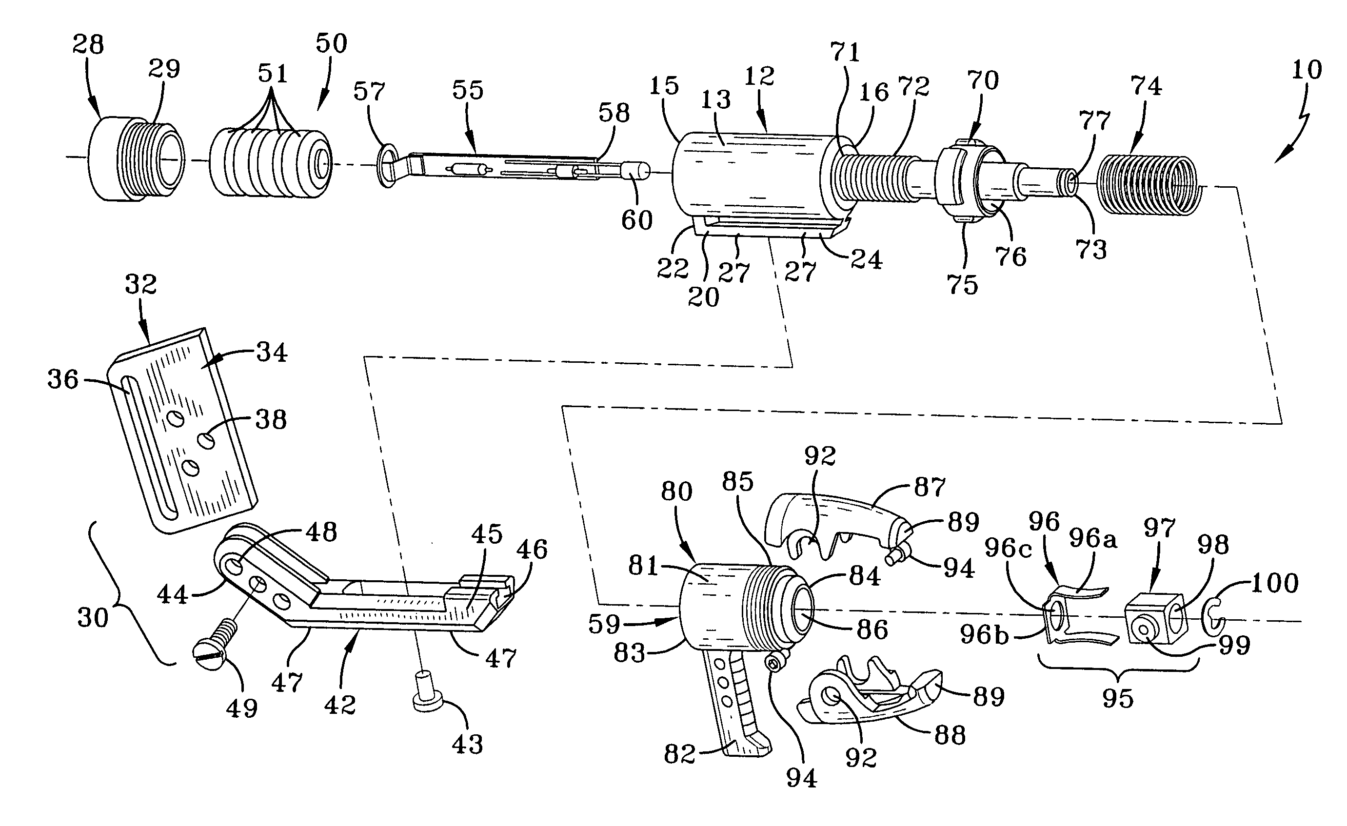
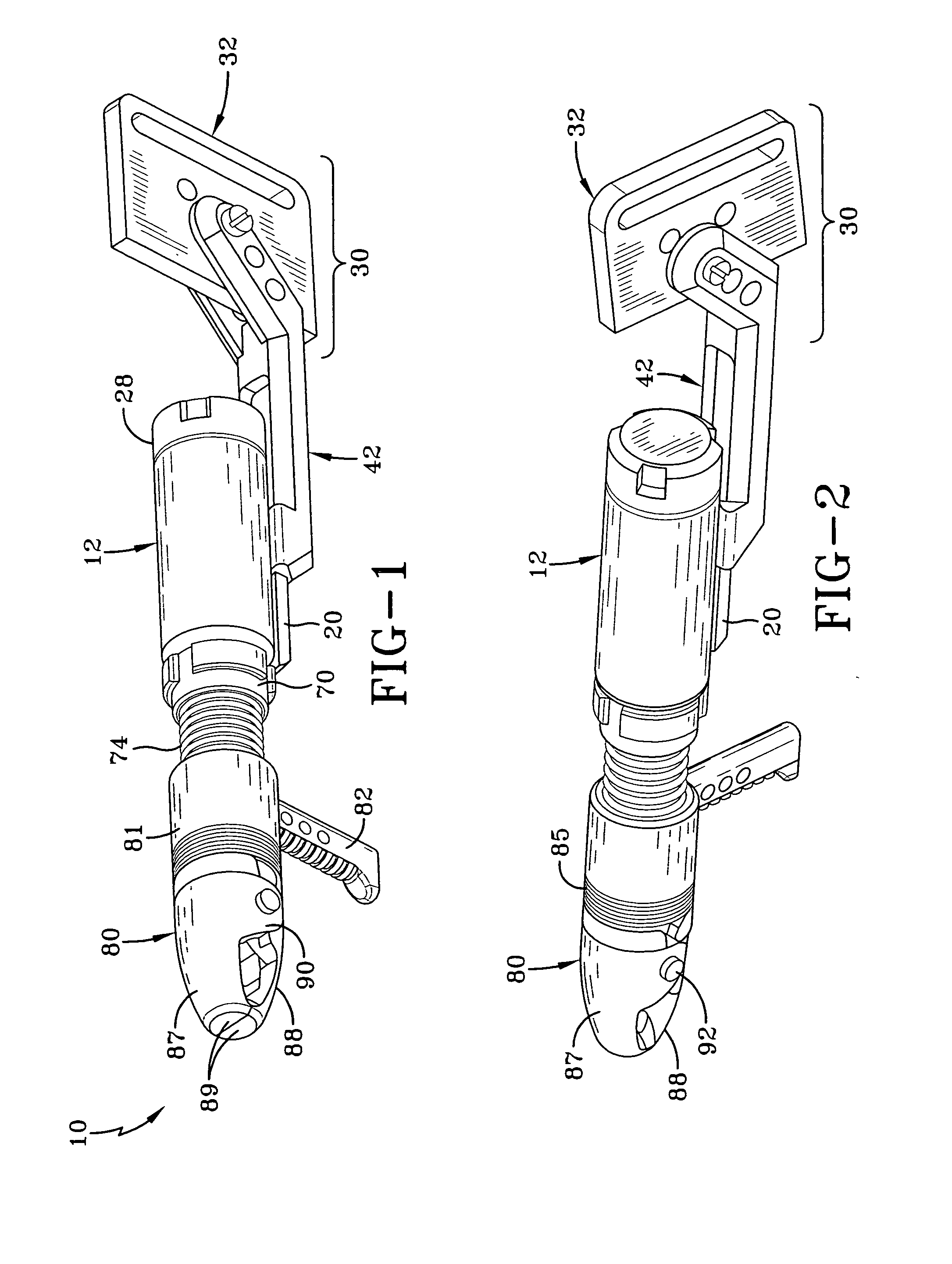
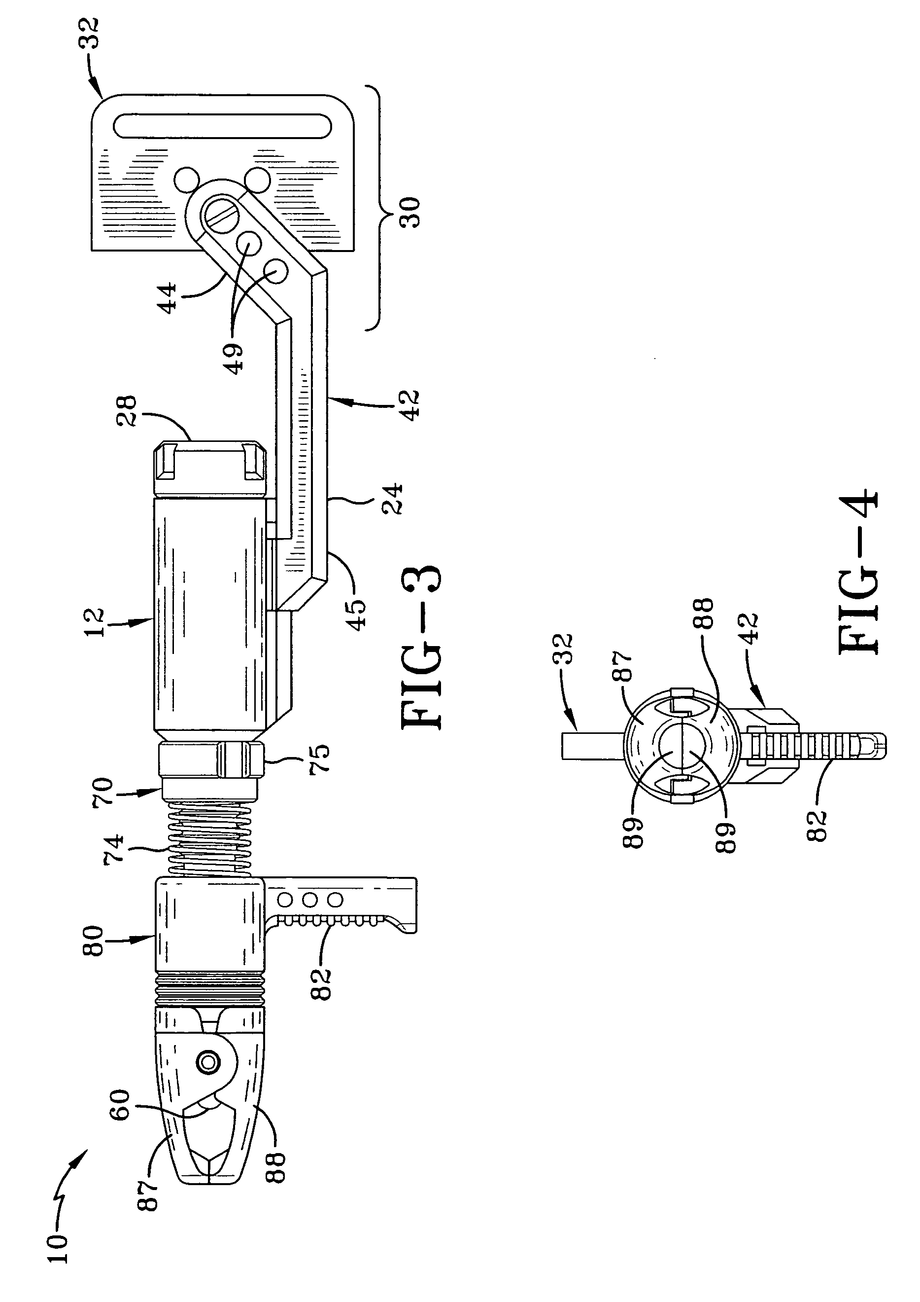
[0030]Having reference to the drawings, attention is directed first to FIG. 1, which discloses the lighted release aid apparatus of the invention, with the release aid apparatus being designated generally by the numeral 10. As can be appreciated by a comparison of FIGS. 1-7, the archery lighted release aid apparatus 10 includes a main body housing 12 having an exterior surface 13 and a main body housing inner channel 14 which extends longitudinally through the main body housing. The main body housing 12 has a first end 15 and a second end 16, with the main body housing channel 14 at the second end 16 having screw-threads 17 for engagement with the screw-threads 29 of cap 28.

[0031]Extending longitudinally along what is shown as the bottom of the archery lighted release aid of the invention is a ridge member 20 having a downwardly depending section 22 and an elongated section 24 spaced a distance from the exterior surface 13 of the main body housing and parallel thereto, with the elon...


PUM


Abstract

An archery lighted release aid apparatus for providing sufficient illumination to assist an archer in attaching the release aid to the bowstring or loop and / or the arrow to the nocking position of the bowstring is provided. The archery lighted release aid apparatus has a light source, a switch assembly connected to said light source, a trigger housing having a trigger housing main body and a trigger, with the trigger housing main body having a channel extending completely therethrough where the switch assembly passes, a main body housing having a first end and a second end, with the main body housing first end having a cap attached thereto, and with the main body housing having a channel extending completely therethrough, a power source located inside the main housing in the main body channel, with the power source contacting the switch assembly, and a wrist strap mounting assembly connected to the main body housing.

Description

BACKGROUND OF THE INVENTION[0001]1. Field of the Invention[0002]This invention relates generally to an archery release aid, and more particularly, to one having an integral light source.[0003]2. Description of the Related Art[0004]Archers hunting in low light conditions, for example, in the early morning, early evening, or in the deep woods, often have difficulty attaching a release aid to the bowstring or loop and / or setting the arrow to the nocking position of the bowstring. The nocking position is the point along the bowstring where the nock on the arrow contacts the string. In theory, under most circumstances when shot, an arrow should be fairly level i.e. essentially perpendicular to the bowstring at rest.[0005]A release aid is a device used in hunting for the past 40-50 years which grips the bowstring and assists in making the arrow fly in a straight path instead of at a slight angle. This is accomplished by aiding in the release of the arrow from the string. Without the use o...

Claims


Application Information

Patent Timeline
IPC IPC(8): F41B5/18
CPCF41G1/34F41B5/1469
Inventor FREITAG, WILLIAM C.BRADEN, ERIC
Owner FREITAG WILLIAM C
Learn More