Heat exchanger

a heat exchanger and heat exchange technology, applied in the field of heat exchangers, can solve the problems of reducing heat exchange efficiency, difficult miniaturization of heat exchangers, poor heat exchange efficiency, etc., and achieve the effect of preventing or reducing the adhesion of impurities and prolonging the li

Inactive Publication Date: 2011-02-17
PANASONIC CORP
View PDF29 Cites 38 Cited by
  • Summary
  • Abstract
  • Description
  • Claims
  • Application Information

AI Technical Summary

Benefits of technology

[0012]An object of the present invention is to provide a heat exchanger in which the adhesion of impurities is prevented or reduced and that can be miniaturized, can be made highly efficient, and can have a longer life, and a washing apparatus including the same.
[0013]Another object of the present invention is to provide a heat exchanger in which the adhesion of impurities is prevented or reduced and that can be miniaturized, and can be made highly efficient, can have a longer life, and can be made lightweight, and a washing apparatus including the same.

Problems solved by technology

This results in reduced heat exchange efficiency.
Therefore, it is difficult to miniaturize the heat exchanger.
Furthermore, heat generated by the heater 803 provided on the outer surface of the base material pipe 801 escapes out of the base material pipe 801, resulting in poor heat exchange efficiency.
Consequently, a material for the spiral core 805 is limited, which makes it difficult to make the heat exchanger lightweight.
However, impurities such as a scale are deposited on the conventional heat exchanger to adhere thereto due to long-term use.
When a large number of fractions of the impurities that have adhered to the heat exchanger are discharged from the heat exchanger, a washing nozzle is clogged, so that washing water cannot be sprayed.
As a result, the life of the sanitary washing apparatus is shortened.
Since the conventional heat exchanger is difficult to miniaturize, a sanitary washing apparatus using the heat exchanger is also difficult to miniaturize.

Method used


Image

  • Heat exchanger
  • Heat exchanger
  • Heat exchanger

Examples


tenth embodiment

[0287]FIG. 14 is a cross-sectional view in the axial direction of a heat exchanger in a tenth embodiment of the present invention. The heat exchanger according to the tenth embodiment differs from the heat exchanger according to the third embodiment in that a plurality of spiral springs 102, 103, and 104 are provided so as not to come into direct contact with an outer peripheral surface of a sheathed heater 7 and an inner peripheral surface of a case 8 and in that a plurality of spring supporting stands 21 for supporting the springs 102, 103, and 104 such that respective ends of the springs 102, 103, and 104 do not come into contact with the inner peripheral surface of the case 8. Also in this case, spiral flow paths 9c, 9e, and 9g are intermittently formed within the case 8, and cylindrical flow paths 9d and 9f are formed thereamong. The springs 102, 103, and 104 function as a flow velocity conversion mechanism, a flow direction conversion mechanism, a turbulent flow generation mec...

eleventh embodiment

[0290]FIG. 15 is a cross-sectional view in the axial direction of a heat exchanger in an eleventh embodiment of the present invention. The heat exchanger according to the eleventh embodiment differs from the heat exchanger according to the ninth embodiment in that a spiral spring 105 is provided in a region RA where the surface temperature of a copper pipe 17 in a sheathed heater 7 becomes not less than a predetermined temperature. The region RA is a region centered on the slightly downward side from the center of the copper pipe 17. In this case, a spiral flow path 9b is formed around the region RA where the surface temperature of the copper pipe 17 within a case 8 becomes not less than a predetermined temperature, and a cylindrical flow path 9a is formed around the other region. The spring 105 functions as a flow velocity conversion mechanism, a flow direction conversion mechanism, a turbulent flow generation mechanism, and an impurity removal mechanism.

[0291]The operation and the...

twelfth embodiment

[0295]FIG. 16 is a cross-sectional view in the axial direction of a heat exchanger in a twelfth embodiment of the present invention. The heat exchanger according to the twelfth embodiment differs from the heat exchanger according to the eleventh embodiment in that a spiral spring 106 is provided in the vicinity of and on the upstream side of a region RA where the surface temperature of a copper pipe 17 in a sheathed heater 7 becomes not less than a predetermined temperature. The region RA is a region centered on the slightly downward side from the center of the copper pipe 17. In this case, a cylindrical flow path 9a is formed around the region RA where the surface temperature of the copper pipe 17 within a case 8 becomes not less than the predetermined temperature, and a spiral flow path 9b is formed in the vicinity of and on the upstream side of the region RA. The spring 106 functions as a flow velocity conversion mechanism, a flow direction conversion mechanism, a turbulent flow ...


PUM


Abstract

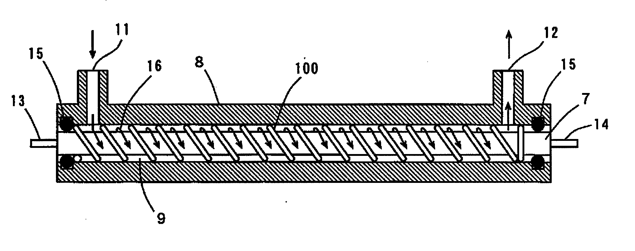
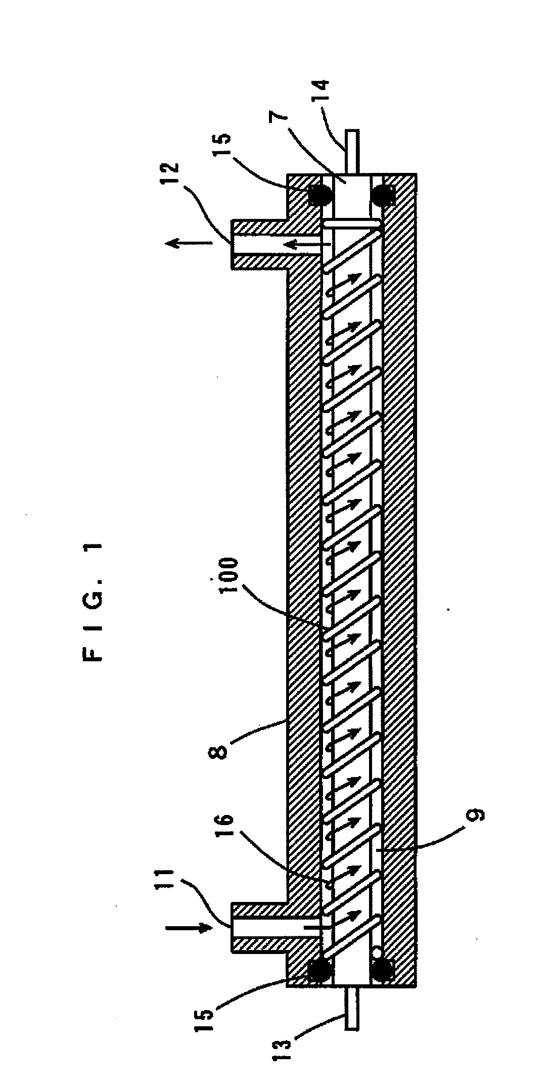
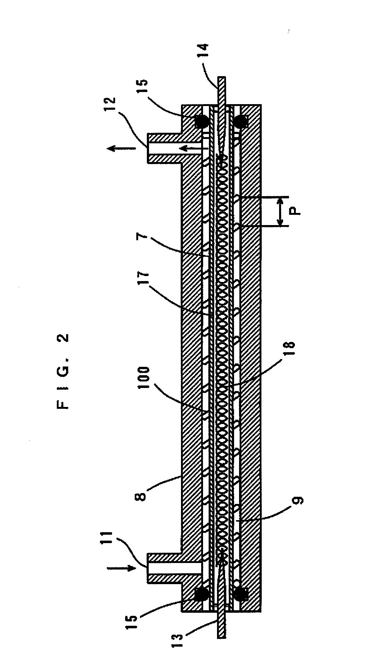
A heat exchanger comprises a substantially pillar sheathed heater, a substantially cylindrical case, and a spiral spring. The sheathed heater is accommodated in the case. The spring is provided so as to be wound around an outer peripheral surface of the sheathed heater. Thus, a spiral flow path is formed among an outer peripheral surface of the sheathed heater, an inner peripheral surface of the case, and the spring. The spring functions as a flow velocity conversion mechanism, a turbulent flow generation mechanism, a flow direction conversion mechanism, and an impurity removal mechanism. A water inlet and a water outlet are respectively arranged at positions eccentric from a central axis of the case on a side surface of the case.

Description

CROSS-REFERENCE TO RELATED APPLICATION[0001]The present application is a division of U.S. application Ser. No. 10 / 596,355, filed Jun. 9, 2006, which is a National Stage Application of PCT / JP2004 / 018389, filed Dec. 9, 2004, the disclosures of which incorporated herein by reference in their entireties, which claim priority of Japanese Patent Application Nos. 2003-411438 filed on Dec. 10, 2003, 2003-411439 filed on Dec. 10, 2003, 2004-34666 filed Feb. 12, 2004, 2004-34665 filed Feb. 12, 2004, 2004-38201 filed on Feb. 16, 2004, 2004-155816 filed May 26, 2004 and 2004-214023 filed on Jul. 22, 2004.TECHNICAL FIELD[0002]The present invention relates to a heat exchanger for heating a fluid and a washing apparatus comprising the same.BACKGROUND ART[0003]Heat exchangers for heating water are used for sanitary washing apparatuses that wash the private parts of the human bodies, clothes washing apparatuses that wash clothes, and dish washing apparatuses that wash dishes (see Patent Document 1)....

Claims


Application Information

Patent Timeline
Patent Type & Authority Applications(United States)
IPC IPC(8): F28F7/00F28F27/00F28F13/12E03D9/08F24H1/10
CPCE03D9/08F24H1/102F28D7/106F28F13/06D06F39/04F24H9/0015F24H9/1818F24H9/2028A47L15/4285F24D19/0092H05B3/50F24H1/10F24H15/45F24H15/174F24H15/238F24H15/25F24H15/265F24H15/219F24H15/37F24H15/32
Inventor SHIRAI, SHIGERUUMEKAGE, YASUHIRONAKAMURA, KAZUSHIGEFURUBAYASHI, MITSUYUKIYASUI, KEIKO
Owner PANASONIC CORP
Why Eureka
Try Eureka