Flexible flat circuitry

a flat circuit and flexible technology, applied in the direction of flat/ribbon cables, insulated conductors, cables, etc., can solve the problems of high signal attenuation, difficult to maintain constant impedance and high signal transfer speed in certain transmission lines, increase the cost of transmission lines, etc., to promote differential signal transmission through transmission lines, improve low impedance, and flexible transmission lines

Inactive Publication Date: 2011-02-17
MOLEX INC
View PDF11 Cites 15 Cited by
  • Summary
  • Abstract
  • Description
  • Claims
  • Application Information

AI Technical Summary

Benefits of technology

[0003]It is therefore an object of the present invention to provide an improved low impedance, flexible transmission line for use in connecting two electronic devices together. Another object of the present invention is to provide a flexible flat circuitry extent having a pattern of signal and ground traces arranged on opposing sides of a substrate that promotes the transmission of differential signals through transmission line.
[0009]The ground traces are aligned with the signal traces (on opposite sides of the support base) so that portions of the signal traces overlap edges of the ground traces or vice-versa. In this manner, the wide ground traces are associated with substantially only their particular pair of differential signal traces. The ground traces are space wider apart from each other than the traces of each differential signal pair, but are more narrowly spaced apart from each other than the spacing between adjacent differential signal pairs. In this manner, impedances of between 90 and 110 ohms can be reliably achieved.

Problems solved by technology

It is difficult to maintain a constant impedance and high signal transfer speeds in certain transmission lines.
When flexible printed circuitry (“FPC”) is used, there is a high signal attenuation.
The multiple layer construction shown in the aforementioned '918 patent may increase the cost of the transmission line.

Method used


Image

  • Flexible flat circuitry
  • Flexible flat circuitry

Examples


Embodiment Construction

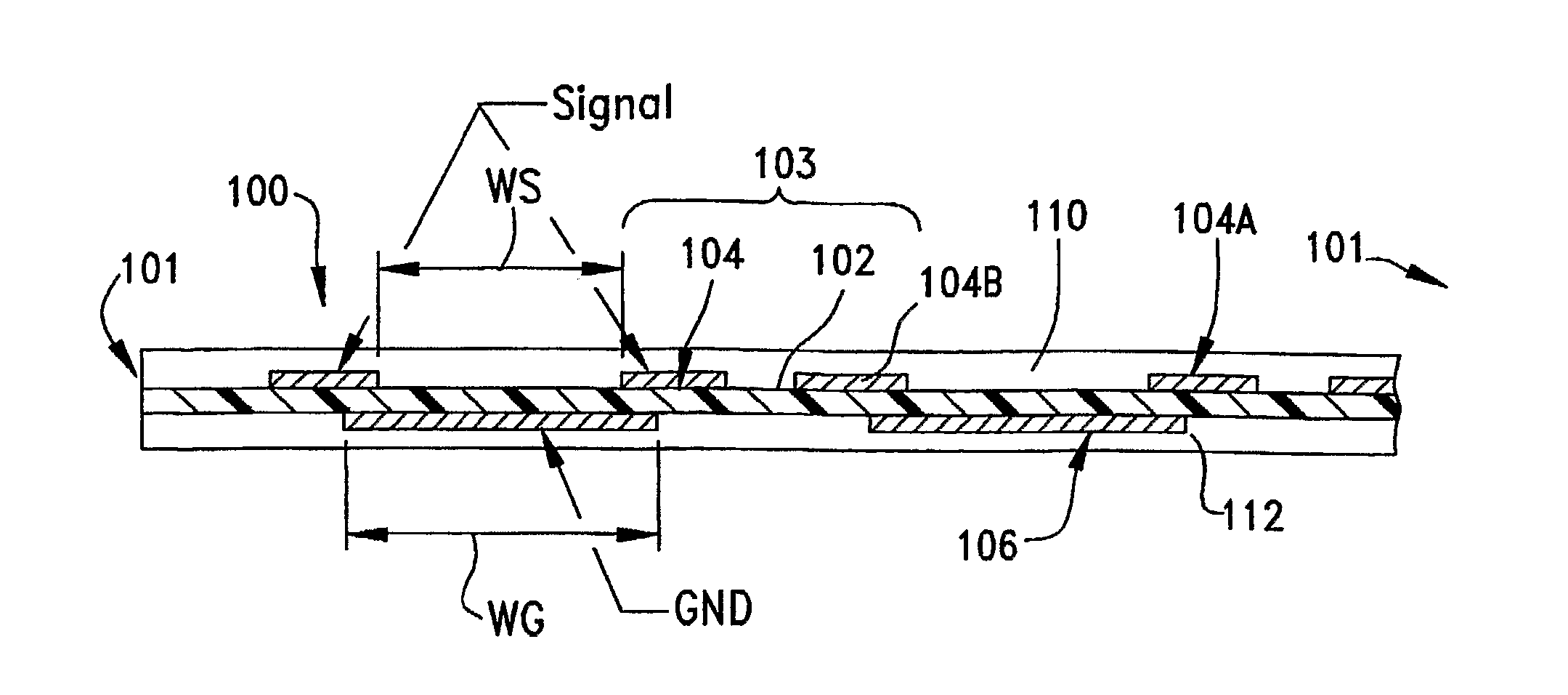
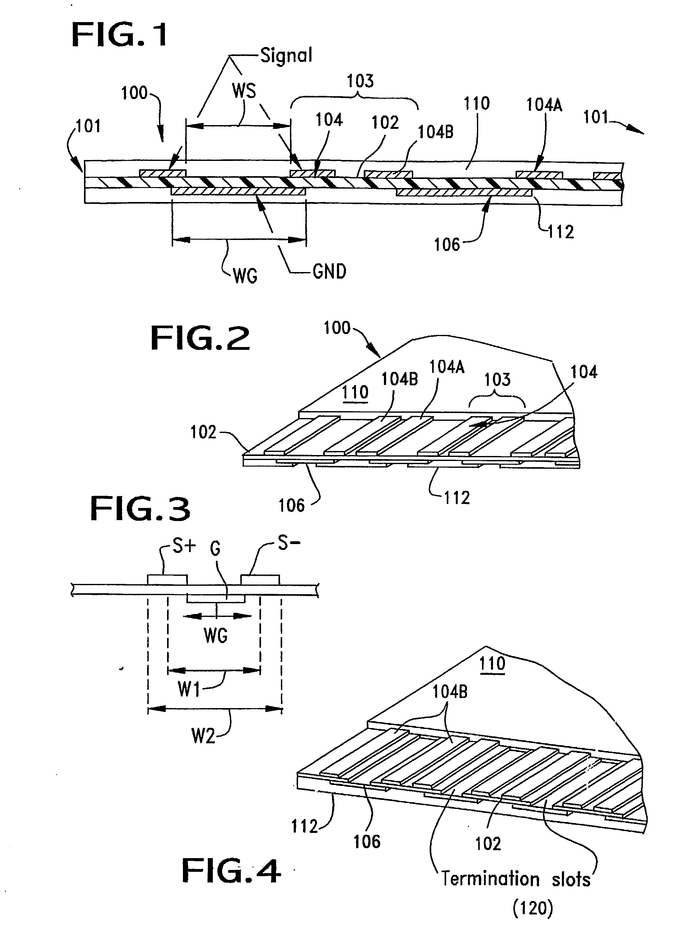
[0016]FIG. 1 illustrates an end view of an extent of FFC that incorporates the transmission lines of the present invention. The transmission line 100 is seen to have a support base, or substrate 102 that has a longitudinal extent between two opposing ends of the FFC and which has two side edges 101. This support base is formed of an insulative material.

[0017]The support base supports a plurality of conductive traces on opposing or top and bottom, as shown, surfaces. The bottom surface is seen in FIG. 1 to support a pair of ground traces, while the upper surface is seen to support five signal traces 104. The signal traces are arranged in pairs of traces, with each pair including traces 104A and 104B, with the pair of signal traces carrying differential signals from a source to a destination.

[0018]The two signal traces 104A, 104B of each pair of signal traces are spaced apart by a preselected distance WS. An associated ground trace 106, or “GND” is disposed on the opposite side of the...


PUM

PropertyMeasurementUnit
impedancesaaaaaaaaaa

Abstract

A transmission line is made from FFC and has an elongated support base with opposing top and bottom sides. The support base has a plurality of conductive traces arranged on both of its side with the traces on one of the support base sides being arranged in pairs of signal traces, and specifically pairs of differential signal traces. The traces which are arranged on the other side of the support base include ground traces, each of which preferably has a width that is greater than the combined width of two signal traces that make up a signal pair. Each of the ground traces are aligned with a pair of signal traces.

Description

BACKGROUND OF THE INVENTION[0001]The present invention is directed generally to conductive transmission lines, and more particularly, flexible transmission lines utilizing flexible flat circuitry (“FFC”)for use in quickly transmitting signals between electronic devices.[0002]One way to transfer signals between electronic devices is to use flat cable that may be twisted and flexed. This type of cable is known as either FFC or flexible flat cable. It is known, as demonstrated, by U.S. Pat. No. 4,798,918, issued Jan. 17, 1989, that one can arrange signal and ground traces in certain patterns to minimize cross talk between adjacent and opposing signal traces. This patent shows individual signal traces flanked by ground traces on each side and by a pair of ground traces on the opposite side of the FFC. It is difficult to maintain a constant impedance and high signal transfer speeds in certain transmission lines. When flexible printed circuitry (“FPC”) is used, there is a high signal atte...

Claims


Application Information

Patent Timeline
Patent Type & Authority Applications(United States)
IPC IPC(8): H01B7/08
CPCH01B7/0838H05K1/0245H05K1/0253H05K2201/09727H05K2201/0352H05K2201/09236H05K2201/09709H05K1/0393
Inventor NODA, ATSUHITONIITSU, TOSHIHIRO
Owner MOLEX INC
Why Eureka
Try Eureka