Input/output electrostatic discharge device with reduced junction breakdown voltage

Inactive Publication Date: 2011-02-17
MEDIATEK INC
View PDF9 Cites 96 Cited by
  • Summary
  • Abstract
  • Description
  • Claims
  • Application Information

AI Technical Summary

Problems solved by technology

While this I / O driver has been used for some generic designs, it has been a continuing challenge to balance ESD protection performance and I / O performance.

Method used


Image

  • Input/output electrostatic discharge device with reduced junction breakdown voltage
  • Input/output electrostatic discharge device with reduced junction breakdown voltage
  • Input/output electrostatic discharge device with reduced junction breakdown voltage

Examples


Embodiment Construction

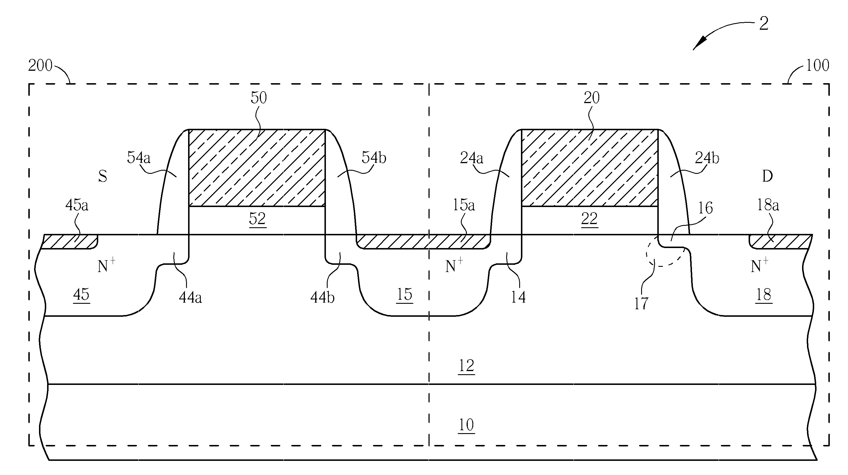
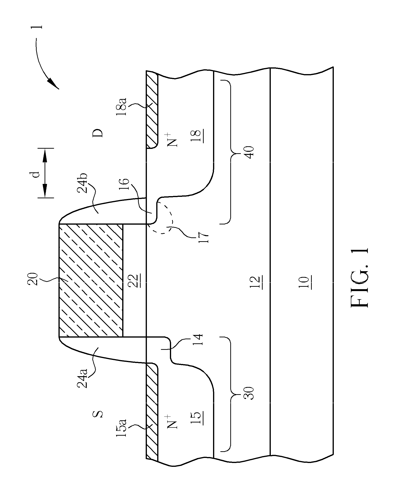
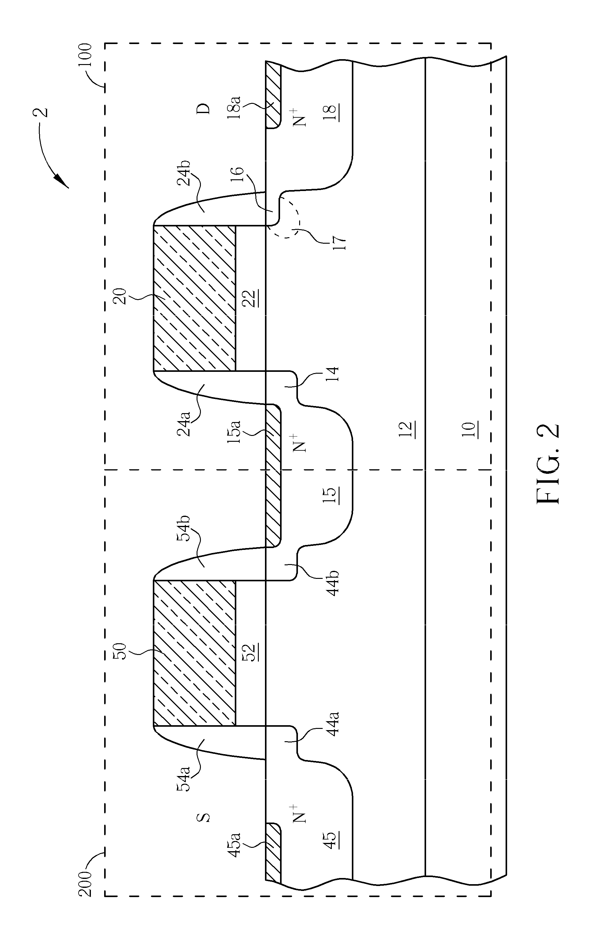
[0015]In the following detailed description of the invention, reference is made to the accompanying drawings which form a part hereof, and in which is shown, by way of illustration, specific embodiments in which the invention may be practiced. These embodiments are described in sufficient detail to enable those skilled in the art to practice the invention. Other embodiments may be utilized and structural, logical, and electrical changes may be made without departing from the scope of the present invention. The following detailed description is, therefore, not to be taken in a limiting sense, and the scope of the present invention is defined only by the appended claims, along with the full scope of equivalents to which such claims are entitled. In the following description and in the claims, the terms “include” and “comprise” are used in an open-ended fashion, and thus should be interpreted to mean “include, but not limited to . . . ”. Also, the term “couple” is intended to mean eith...


PUM


Abstract

An I/O electrostatic discharge (ESD) device having a gate electrode over a substrate, a gate dielectric layer between the gate electrode and the substrate, a pair of sidewall spacers respectively disposed on two opposite sidewalls of the gate electrode, a first lightly doped drain (LDD) region disposed under one of the sidewall spacers, a source region disposed next to the first LDD region, a second LDD region disposed under the other sidewall spacer, and a drain region disposed next to the second LDD region, wherein a doping concentration of the second LDD region is larger than a doping concentration of the first LDD region.

Description

BACKGROUND OF THE INVENTION[0001]1. Field of the Invention[0002]The present invention relates generally to integrated circuits (IC's) and, more particularly to an input / output (I / O) electrostatic discharge (ESD) device with lower junction breakdown voltage and better ESD protection performance.[0003]2. Description of the Prior Art[0004]An IC chip electrically communicates with off-chip electronics to exchange information. The IC chip may employ different voltages than are employed by off-chip electronics. Accordingly, the interface between the IC chip and off-chip electronics must accommodate the voltage differences. One such interface includes a mixed voltage I / O driver.[0005]A conventional ESD protection structure includes two NMOS transistors in a cascode configuration, where the two NMOS transistors are merged into the same active area of a substrate. For example, the two NMOS transistors allow a 5V signal to be dropped to 3.3V during normal operation while providing a parasitic...

Claims


Application Information

Patent Timeline
Patent Type & Authority Applications(United States)
IPC IPC(8): H01L27/088H01L29/78
CPCH01L27/0266H01L29/1045H01L29/1083H01L29/66659H01L29/41775H01L29/665H01L29/6659H01L29/7835
Inventor LEE, TUNG-HSINGLIN, I-CHENGTSAO, WEI-LI
Owner MEDIATEK INC
Why Eureka
Try Eureka