Inverter controller, compressor, and electric home appliance

a technology for inverter controllers and electric home appliances, applied in the direction of electronic commutators, motor/generator/converter stoppers, dynamo-electric converter control, etc., can solve the problem of inability to output a desirable voltage, the work range of the inverter is reduced, and the inverter cannot respond well to sharp acceleration or sharp deceleration, so as to eliminate the miss in sensing the position of the magnetic pole. , the effect o

Inactive Publication Date: 2011-02-17
PANASONIC CORP
View PDF9 Cites 36 Cited by
  • Summary
  • Abstract
  • Description
  • Claims
  • Application Information

AI Technical Summary

Benefits of technology

[0059]The foregoing structure allows the conduction angle of the inverter circuit to be reduced in a range greater than a lower limit of a given angle range in electric angles at the following case: a time difference between the intervals between each of the position senses by the positi...

Problems solved by technology

During this uncontrolled range, the inverter cannot output a desirable voltage, so that a utilization ratio of the DC voltage by the inverter is obliged to stay at a low level.
This low utilization ratio causes a low terminal voltage of the DC brushless motor, thereby decreasing the work range of the motor, namely, the max. rpm is obliged to stay at a low level.
As a result, the art shown in FIG. 13 poorly responds to a sharp acceleration or a sharp deceleration because it employs integrator 12 having a phase delay of 90 degree.
However, the use of the integrator incurs a delay of 90 degree in electric angles, so...

Method used


Image

  • Inverter controller, compressor, and electric home appliance
  • Inverter controller, compressor, and electric home appliance
  • Inverter controller, compressor, and electric home appliance

Examples


second embodiment

[0160]FIG. 4 shows a block diagram of an inverter controller in accordance with the present invention. FIG. 5 shows signal waveforms of respective sections of the inverter controller shown in FIG. 4. FIG. 6 shows a flowchart illustrating the work done by the inverter controller shown in FIG. 4.

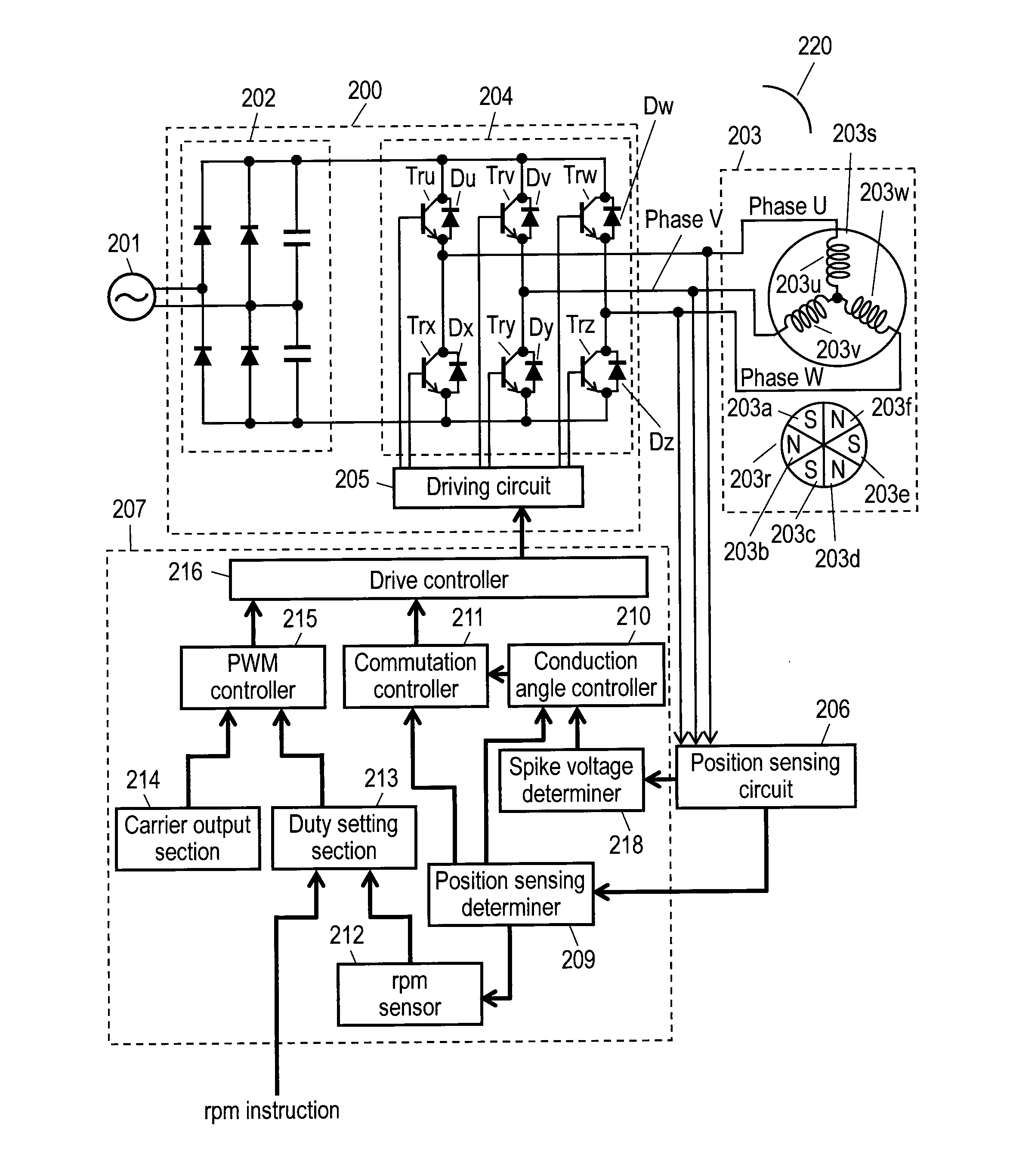
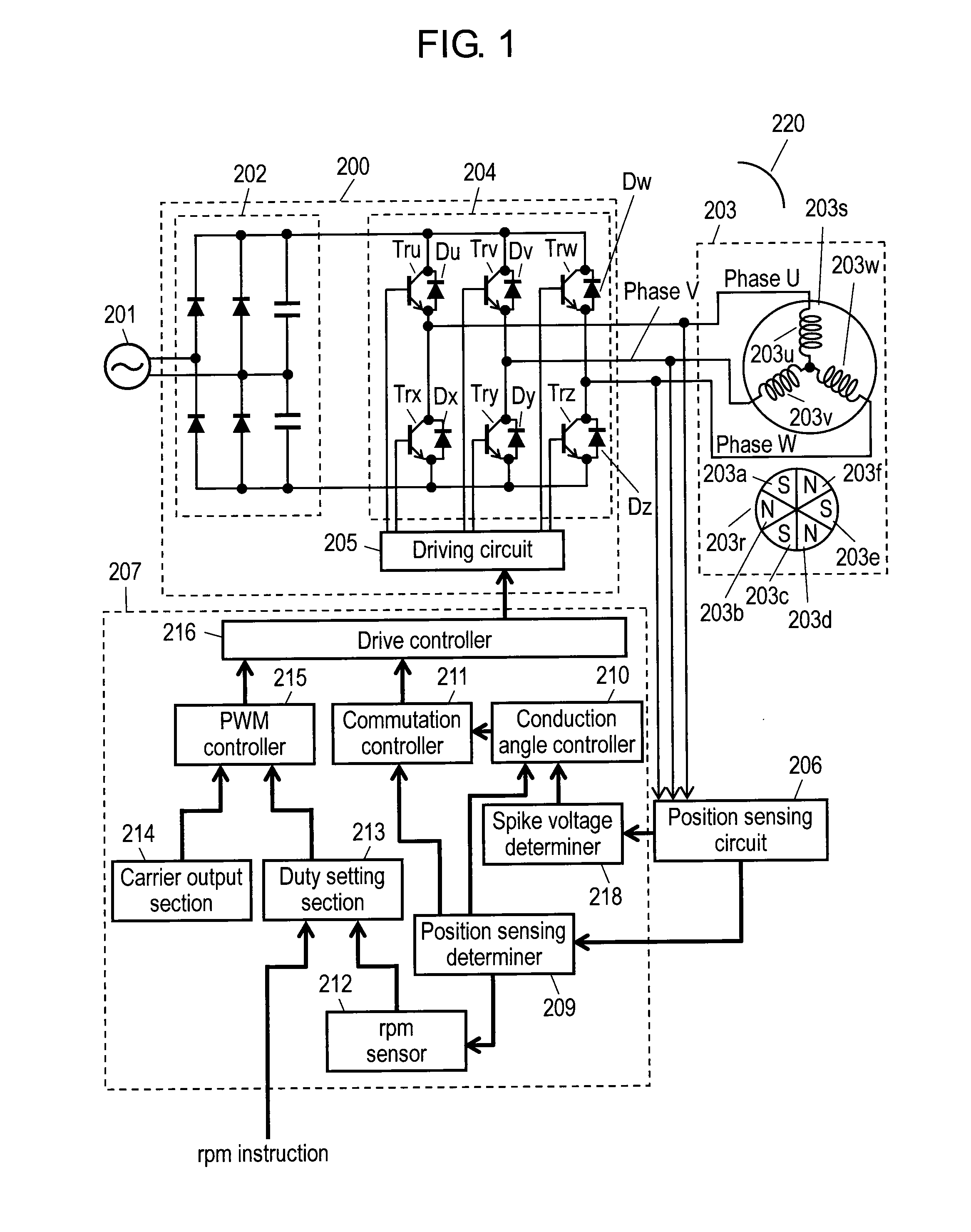
[0161]In FIG. 4, inverter controller 200 connects to commercial power source 201 and a compressor (not shown), and includes rectifier 202 and inverter circuit 204. Rectifier 202 converts commercial power source 201 into a DC power source, and inverter circuit 204 drives brushless DC motor 203 of the compressor. Inverter controller 200 further includes driving circuit 205 that drives inverter circuit 204, position sensing circuit 206 that senses a terminal voltage of motor 203, and microprocessor 207 that controls inverter circuit 204.

[0162]Microprocessor 207 includes position sensing determiner 209 that senses a magnetic pole position of motor 203 based on an output signal from position sensin...

third embodiment

[0218]FIG. 7 shows a block diagram of an inverter controller in accordance with the present invention. FIG. 8 shows signal waveforms of respective sections of the inverter controller shown in FIG. 7. FIG. 9 shows a flowchart illustrating the work done by the inverter controller shown in FIG. 7.

[0219]In FIG. 7, inverter controller 200 connects to commercial power source 201 and a compressor (not shown), and includes rectifier 202 and inverter circuit 204. Rectifier 202 converts commercial power source 201 into a DC power source, and inverter circuit 204 drives brushless DC motor 203 of the compressor. Inverter controller 200 further includes driving circuit 205 that drives inverter circuit 204, position sensing circuit 206 that senses a terminal voltage of motor 203, and microprocessor 207 that controls inverter circuit 204.

[0220]Microprocessor 207 includes position sensing determiner 209 that senses a magnetic pole position of motor 203 based on an output signal from position sensin...

fourth embodiment

[0271]FIG. 10 shows a block diagram of an inverter controller in accordance with the present invention, and FIG. 11 shows a flowchart illustrating the work done by the inverter controller shown in FIG. 10.

[0272]In FIG. 10, position sensing determiner 209 is equipped with both of conduction angle reduction number determiner 209a used in embodiment 2 and conduction angle increase number determiner 209b used in embodiment 3. The inverter controller in accordance with this fourth embodiment thus can produce both of the advantages described in embodiments 2 and 3.

[0273]To be more specific, the second embodiment produces this advantage: If a spike voltage width is increased because of a change in the motor current caused by a change in load torque, a reduction in the conduction angle allows reducing the motor current. As a result, the position sensible range can be increased. At the same time, the spike voltage width can be reduced. This mechanism allows preventing the motor from falling ...


PUM


Abstract

An inverter controller reduces a conduction angle of inverter circuit (204) within a range greater than 120 degree in electric angles when a time difference between intervals between each of position sensing and a total time of a time from an occurrence of a position sensing signal until the start of a commutation work to be done by inverter circuit (204) plus a time duration of a spike voltage becomes shorter than a predetermined reference time. This reduction of the conduction angle allows increasing a position sensible range, so that a position of magnetic poles of a rotor cannot be missed. The inverter controller thus can prevent a motor from falling into out-of-sync caused by a change in load or in voltage.

Description

TECHNICAL FIELD[0001]The present invention relates to inverter controllers to be used in brushless DC motors. It also relates to compressors and electric home appliances such as a refrigerator.BACKGROUND ART[0002]A conventional inverter controller has carried out a wide angle control in which a conduction angle is increased up to 120 degree in electrical angles for increasing a work range of an inverter, thereby boosting an output of the inverter controller. Patent Document 1 discloses an example of such inverter controllers.[0003]A conduction waveform of 120 degree in electric angles has been generally employed because it allows the inverter to be controlled with ease. In a driving system of a brushless DC motor, switches of respective phases of the inverter are conductive only in the range of 120 degree in electric angles although 180 degree is available. The range of remaining 60 degree is thus left uncontrolled.[0004]During this uncontrolled range, the inverter cannot output a d...

Claims


Application Information

Patent Timeline
IPC IPC(8): H02P6/18H02P6/06H02P6/08H02P6/182
CPCH02P6/182H02P6/142H02P6/15
Inventor KODA, ATSUSHIOGAHARA, HIDEHARU
Owner PANASONIC CORP
Why Eureka
Try Eureka