Surgical microscope having an illuminating arrangement

a technology of illuminating arrangement and surgical microscope, which is applied in the field of surgical microscope, can solve the problems of reducing the free work space under the surgical microscope, and the difficulty of sterile manipulation of the corresponding slit illuminating module in day to day surgery, and achieves the effect of minimizing the structural space of the illuminating arrangemen

Active Publication Date: 2011-02-17
CARL ZEISS MEDITEC AG
View PDF18 Cites 31 Cited by
  • Summary
  • Abstract
  • Description
  • Claims
  • Application Information

AI Technical Summary

Benefits of technology

[0026]These measures minimize the structural space f...

Problems solved by technology

However, such a silt illuminating module reduces the free work space under the surgical microscope.
Acco...

Method used


Image

  • Surgical microscope having an illuminating arrangement
  • Surgical microscope having an illuminating arrangement
  • Surgical microscope having an illuminating arrangement

Examples


Embodiment Construction

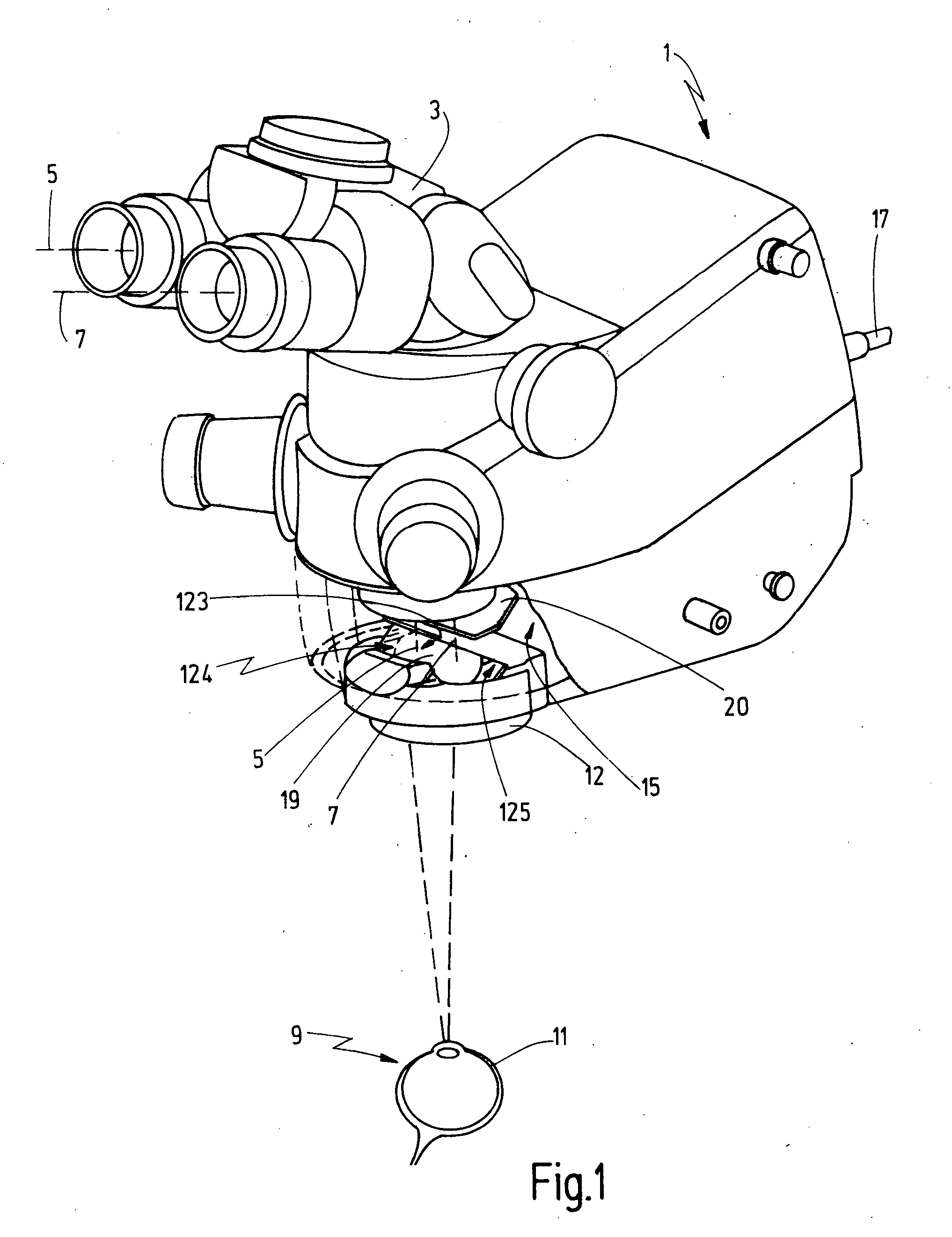
[0036]The ophthalmologic surgical microscope 1 is shown in FIG. 1 and has a binocular tube 3 and a microscope main objective 12. A viewing person can view a patient eye 11 in an object region 9 under magnification through the binocular tube 3 with stereoscopic component beam paths (5, 7).

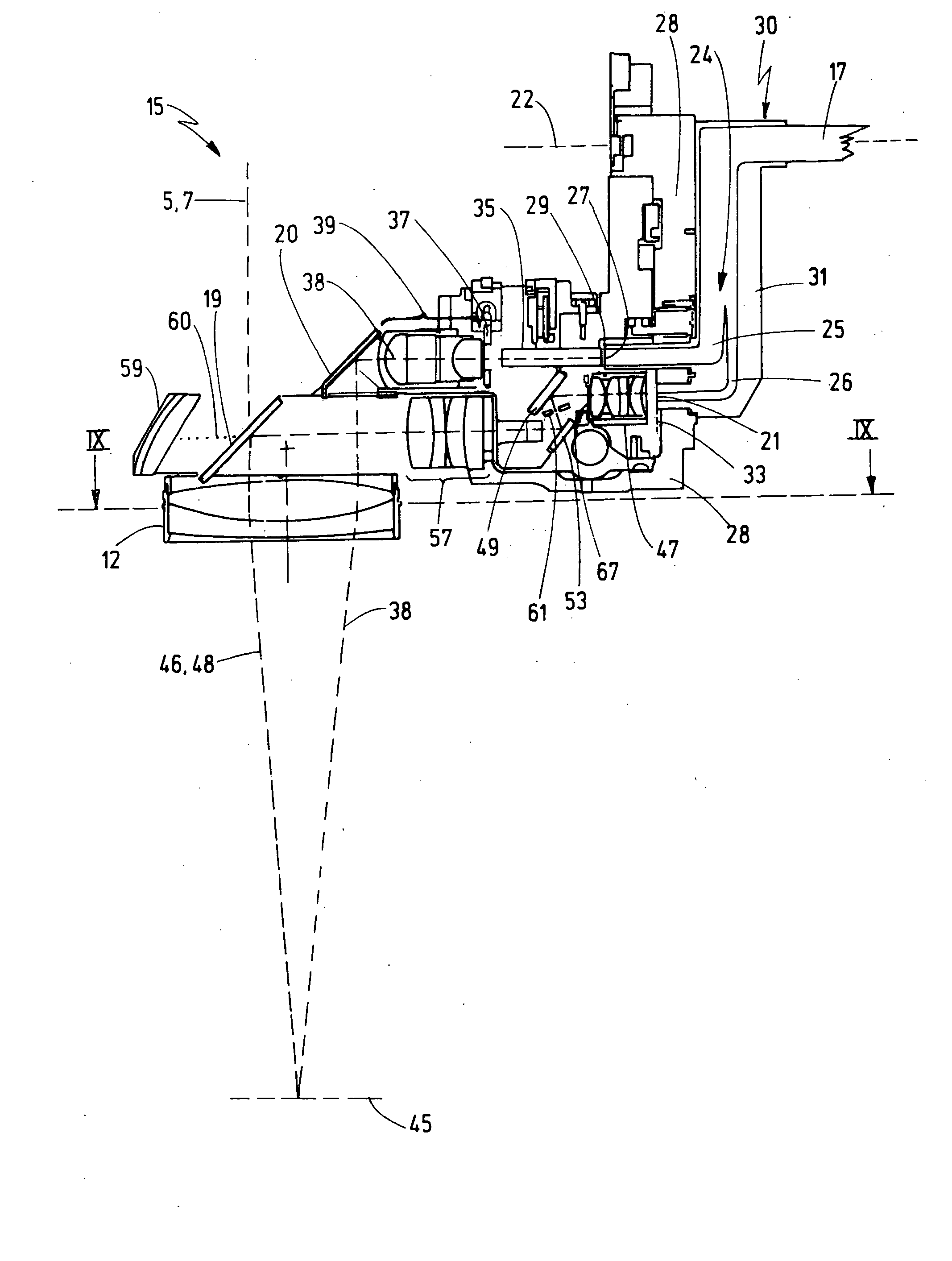
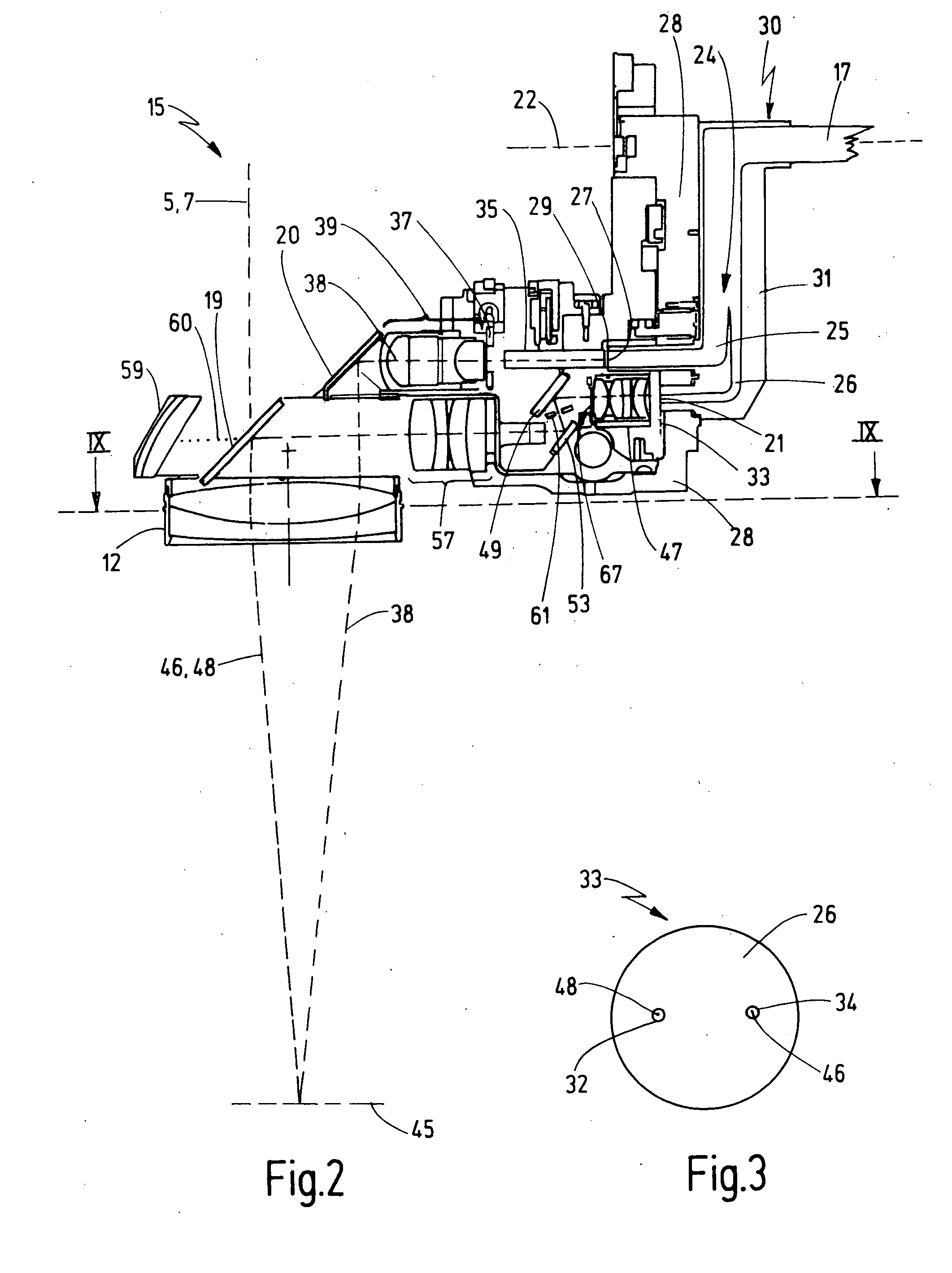
[0037]The ophthalmologic surgical microscope 1 is accommodated on a stand (not shown). The ophthalmologic surgical microscope 1 has an illuminating arrangement 15. The illuminating arrangement 15 is supplied with light via a light conductor 17 from a light source mounted on the stand of the ophthalmologic surgical microscope. The illuminating arrangement 15 includes an illuminating optic having an illuminating mirror 19 and an illuminating mirror 20. The illuminating light is directed through the microscope main objective 12 to the object region 9 via the illuminating mirrors (19, 20).

[0038]The illuminating mirror 19 has a partially mirrored region 123 and first and second fully mirrored regions (12...


PUM


Abstract

The invention relates to a surgical microscope (1) having a microscope main objective (12) for the visualization of an object plane (45) in an object region (9). The microscope main objective (12) is passed through by a first stereoscopic component beam path (5) and by a second stereoscopic component beam path (7). The ophthalmologic surgical microscope (1) includes an adjustable illuminating arrangement (15) which makes illuminating light available. The illuminating arrangement (15) has an illuminating optic having a beam deflecting unit (19) which is mounted on the side of the microscope main objective (12) facing away from the object region (9) in order to direct the illuminating light through the microscope main objective (12) to the object region (9). In a first position of the illuminating arrangement (15), the illuminating light passes through the cross sectional area (89) of the microscope main objective (12) in an area section (91, 92), which at least partially surrounds the optical axis of the first stereoscopic component beam path (5) and/or the optical axis of the second stereoscopic component beam path (7). According to the invention, in an at least one further position of the illuminating arrangement (15), the illuminating light passes through the cross sectional area (89) of the microscope main objective (12) in a surface section (93, 95) whose area centroid (97, 99) is spaced from the optical axis of a stereoscopic component beam path (5, 7) by more than the stereo basis (101) of the two stereoscopic component beam paths (5, 7) from the optical axis of the other stereoscopic component beam paths (7, 5).

Description

CROSS REFERENCE TO RELATED APPLICATIONS[0001]This application claims priority of U.S. provisional application Ser. No. 61 / 272,039, filed Aug. 11, 2009, and also claims priority of German patent application no. 10 2009 036 913.9, filed Aug. 11, 2009, and the entire contents of both of the above applications are incorporated herein by reference.FIELD OF THE INVENTION[0002]The invention relates to a surgical microscope having a microscope main objective for the visualization of an object plane in an object region. The microscope main objective is passed through by a first stereoscopic component beam path and a second stereoscopic component beam path. The surgical microscope further includes an adjustable illuminating arrangement having an illuminating optic with a beam deflection unit mounted on the side of the microscope main objective facing away from the object region in order to direct the illuminating light through the microscope main objective to the object region. In a first pos...

Claims


Application Information

Patent Timeline
IPC IPC(8): G02B21/22
CPCA61B3/10A61B19/5202G02B21/082G02B21/0012A61B19/5223A61B90/30A61B90/20
Inventor ABELE, ALFONSREIMER, PETERNEGELE, ANDREASMERZ, FRANZLIEGEL, JURGEN
Owner CARL ZEISS MEDITEC AG
Why Eureka
Try Eureka