
Flexible Arms of Low Footprint and High Weight-bearing

a flexible arm and high-weight technology, applied in the field of flexible arms, can solve the problems of low weight-bearing, unidirectional weight force unidirectional orientation of ineffective counteracting of unidirectional weight force circular orientation of structural elements, so as to increase the weight-bearing effect and reduce the footprint of flexible arms

Inactive Publication Date: 2011-02-17
XHUNGA ILO KRISTO
View PDF18 Cites 25 Cited by
  • Summary
  • Abstract
  • Description
  • Claims
  • Application Information

AI Technical Summary

Benefits of technology

The patent describes a new method for designing flexible arms that can better bear weight and reduce the space they take up. The method involves creating new arm structures that match the direction of weight forces and increase the weight-bearing capacity of the arm. The new arm structures have a vertically elongated cross section, which increases their weight-bearing without restricting access to the load site. The method also involves combining two different goosenecks with different cross sections in a way that increases the weight-bearing and allows for easy bending. The patent describes several embodiments of the new arm structures and how they can be used in different apparatus applications, such as supporting lighting devices, manipulating optical lenses, and transporting water through the interior channel of the gooseneck.

Problems solved by technology

Conventional arm designs that are circular in cross section do not match the weight forces that are unidirectional.
Circular orientation of structural elements is ineffective at counteracting the unidirectional orientation of weight forces.
This circular-unidirectional mismatch is the main reason behind the conventional arm drawbacks such as the bulkiness, heavy arm weight, low weight-bearing, and large footprint that unduly restrict the user's working space.

Method used


Image

  • Flexible Arms of Low Footprint and High Weight-bearing
  • Flexible Arms of Low Footprint and High Weight-bearing
  • Flexible Arms of Low Footprint and High Weight-bearing

Examples


embodiments

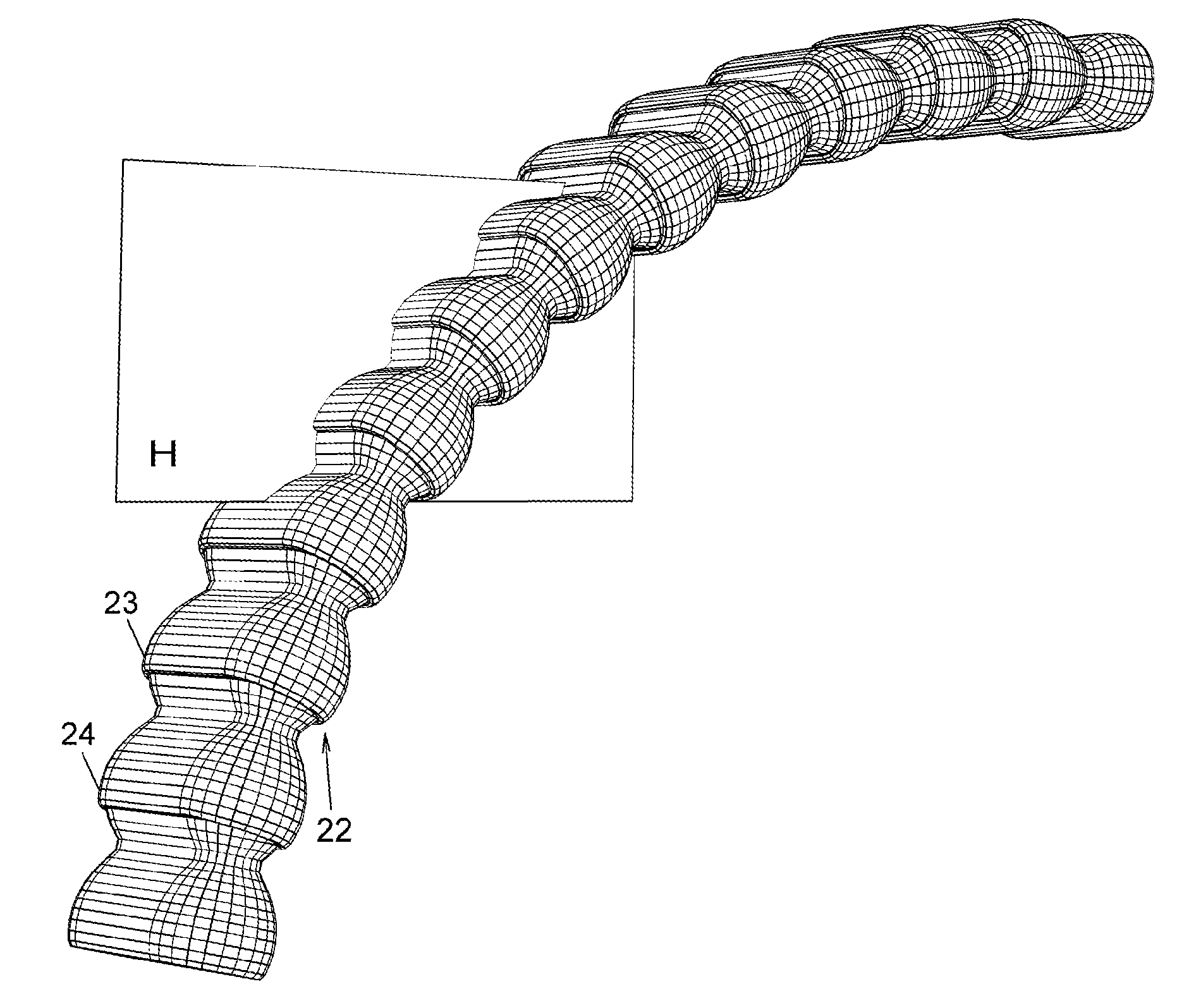
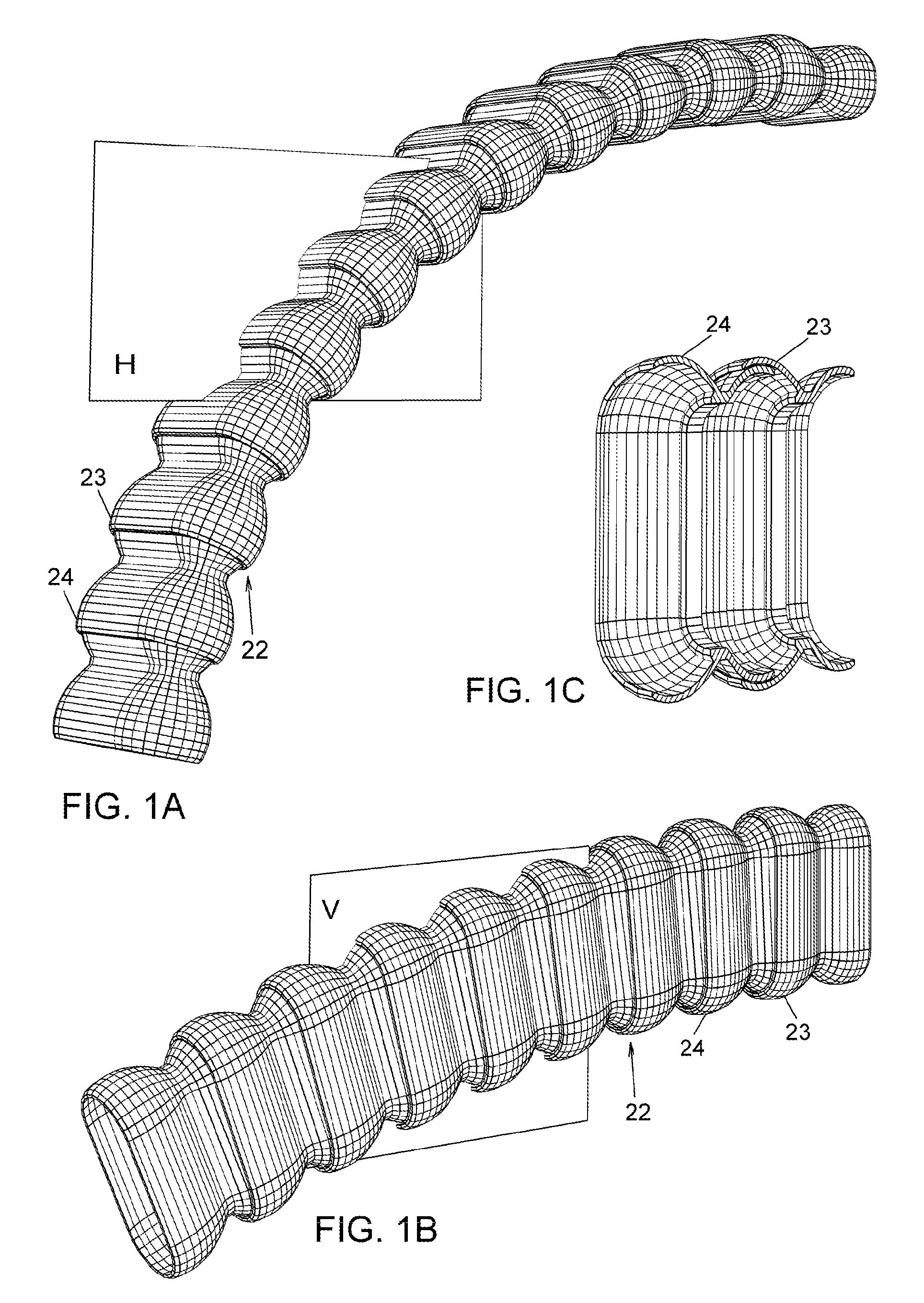
[0044]Flexible arms are bendable structures that can be reconfigured by applying force on the parts of the arm. Embodiment 22 is a novel flexible arm of joined beads. It is easily bendable and reconfigured by the hands of the user in three dimensions. While the entire bending of arm 22 shown in FIG. 1A lays on the horizontal plane H, the whole bending of arm 22 in FIG. 1B lays on the vertical plane V.

[0045]Novel arm embodiment 22 comprises a plurality of joined beads 23 and 24. Each bead has an arcuate tail portion of reduced size formed therein, whose outer surface enters and frictionally engages with the arcuate inner surface of the head portion of a contiguous or immediately adjacent bead. In other words, the outer surface of a bead is engaged with the inner surface or recess of a contiguous bead. Thus, head-to-tail mating beads of the flexible arm have swivel joints. Mating beads can swivel by sliding against one another when forced by the user's hand(s). The arm is simple and r...


PUM


Abstract

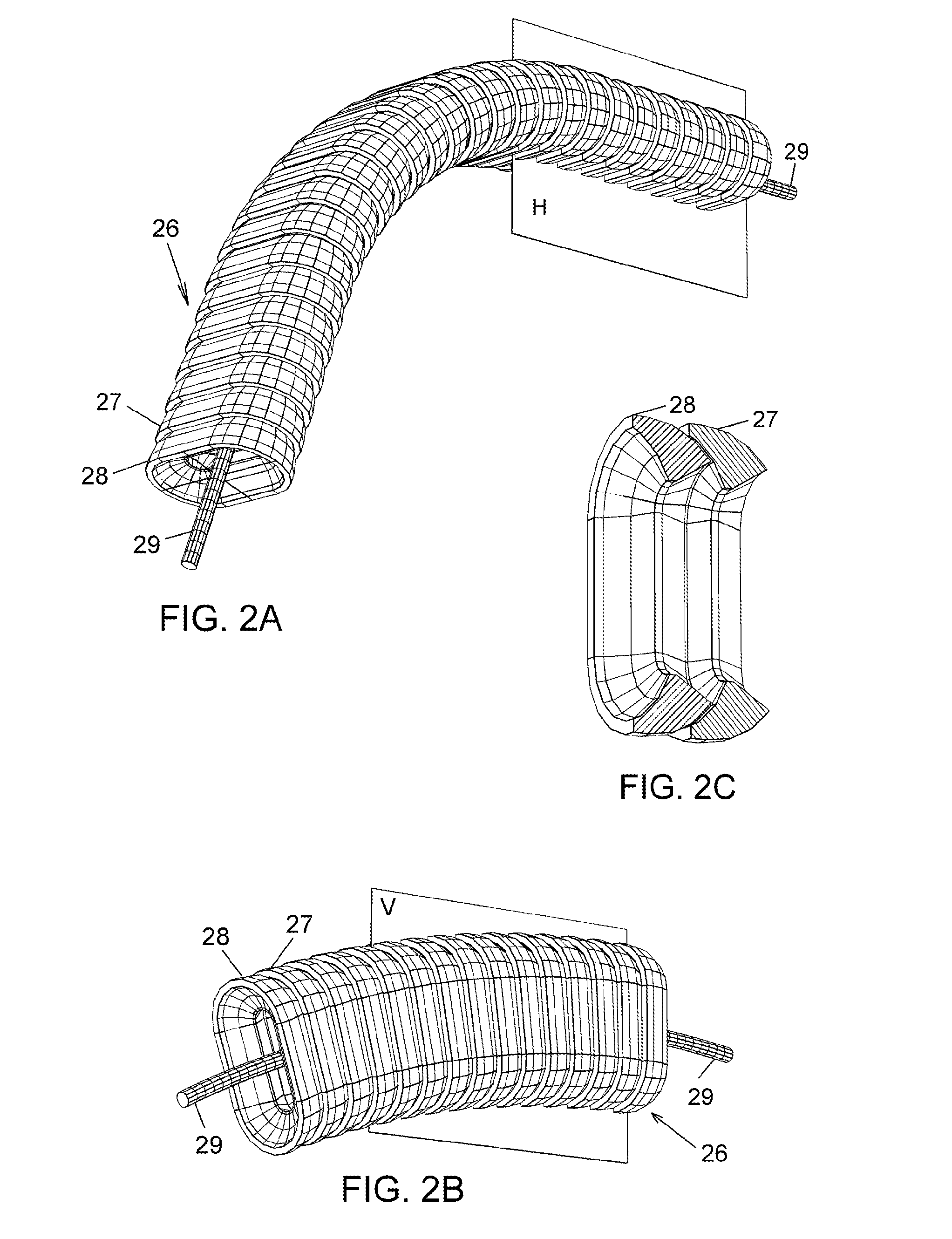
Flexible arms with structural features revealed by embodiments (22), (26), (30), (34), (38), (50), and (52). Flexible arms have cross sections perpendicular to the longitudinal axis that are elongated in the vertical direction, cross sections being longer in size vertically than horizontally. The above flexible arms are referred generically as novel arms (38). Structures of novel arms (38) derive from the detailed analysis of forces and torques exerted on loaded arms at work. To provide full adjustments of the arms in three dimensions, novel arms (38) are joined linearly with circular arms (46) into combined arms (54) as shown in several exemplifying applications. Other specific applications may employ arms (38) alone. Novel arms (38) and (54) have increased weight-bearing and reduced footprints compared to the prior art.

Description

PRIORITY[0001]This application claims priority of U.S. 61 / 229,987, filed on Jul. 30, 2009.TECHNICAL FIELD[0002]This invention relates to flexible arms, more specifically to the structural features of flexible arms.BACKGROUND ART[0003]Flexible arms are often called bendable arms, goosenecks, curvilinear articulating arms, articulable columns, flexible stems, lockable articulating columns, or linkage assemblies. Flexible arms are made of a series of interconnected parts, often called pieces, segments, sections, joints, links, beads, arm members, hollow members, balls and sockets, balls and sleeves, or spirally-wound coil turns. The first of the two ends of a flexible arm is firmly or otherwise attached to a distal support, while the second end holds an object at a proximal position that can be adjusted by the user. Flexible arms have many applications. They support objects, articles, or instruments. Flexible arms are further used for positioning tools, providing passageways for electr...

Claims


Application Information

Patent Timeline
Patent Type & Authority Applications(United States)
IPC IPC(8): F16M13/00F21V19/02G02B7/02E03C1/00
CPCE03C1/06E03C1/066F16M11/06F21V21/32F21S8/081F21V21/108F21V21/28F16M11/40F16G13/16
Inventor XHUNGA, ILO KRISTO
Owner XHUNGA ILO KRISTO
Learn More