Assembly structure for LED lamp

a technology for led lamps and assembly structures, which is applied in the direction of semiconductor devices for light sources, lighting and heating apparatus, lighting support devices, etc., can solve the problems of operator losing screws, inconvenient operation, and the like, and achieves the effect of fast and easy assembly, simple and easy operation

Active Publication Date: 2011-02-17
KITAGAWA HLDG
View PDF3 Cites 64 Cited by
  • Summary
  • Abstract
  • Description
  • Claims
  • Application Information

AI Technical Summary

Benefits of technology

[0009]The present invention is to provide an assembly structure for a LED lamp, whereby the operator can assemble or detach the LED lamp directly without any tool.
[0013](I) Since the cover plate and the LED module can be connected with each other by means of the fasteners, the operator can assemble or detach the LED lamp without using any tools. Thus, the operation is very simple and easy.
[0014](II) Since the locking flanges of the mask can be inserted into the slots of the cover plate, both the mask and the cover plate are not provided with any screw holes. Thus, not only the assembly is fast and easy, but also the problem existed in prior art that the plastic-made mask may be damaged during the tightening of screws can be prevented.

Problems solved by technology

However, the transparent mask and the metallic heat-dissipating cover are made of different material, so that they usually need to be assembled together by screw elements.
However, in practical, the conventional LED lamp still has some problems.
Thus, the operation is very inconvenient.
Even, the operator may lose the screws.
On the other hand, since the transparent mask is a thin component made by plastic materials, the screw holes provided in the plastic-made transparent mask may be damaged due to the excessive force exerted by the operator when he assembles the LED lamp by screw elements.
In this situation, it would become more difficult to assemble the whole set of the LED lamp.
Even, the whole set of the LED lamp has to be replaced by a new set just because of a damaged transparent mask.

Method used


Image

  • Assembly structure for LED lamp
  • Assembly structure for LED lamp
  • Assembly structure for LED lamp

Examples


Embodiment Construction

[0022]The characteristics and technical contents of the present invention will be described with reference to the accompanying drawings. However, the drawings are illustrative only but not used to limit the present invention.

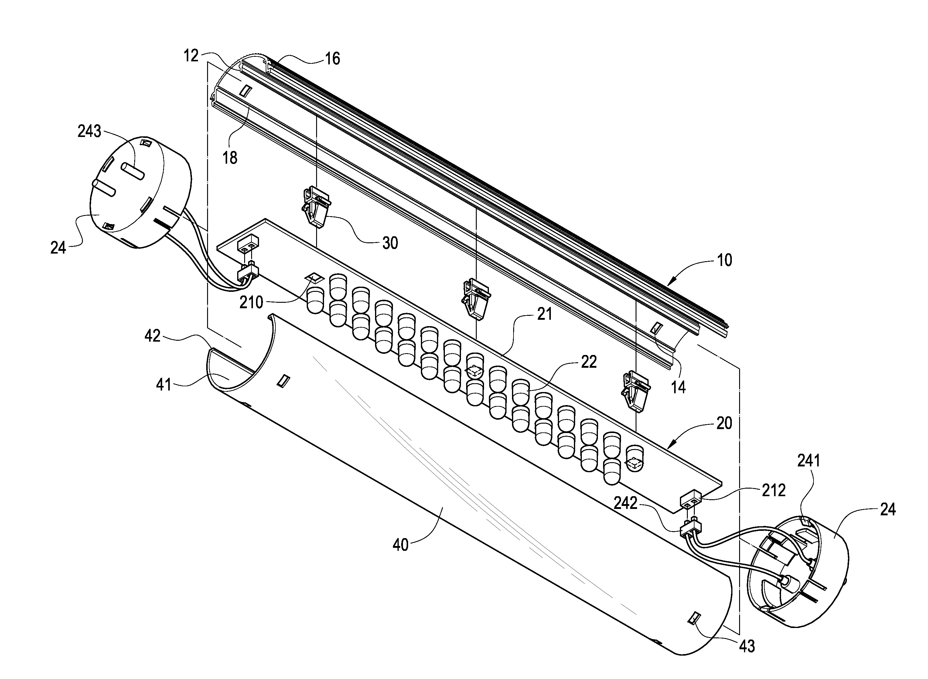
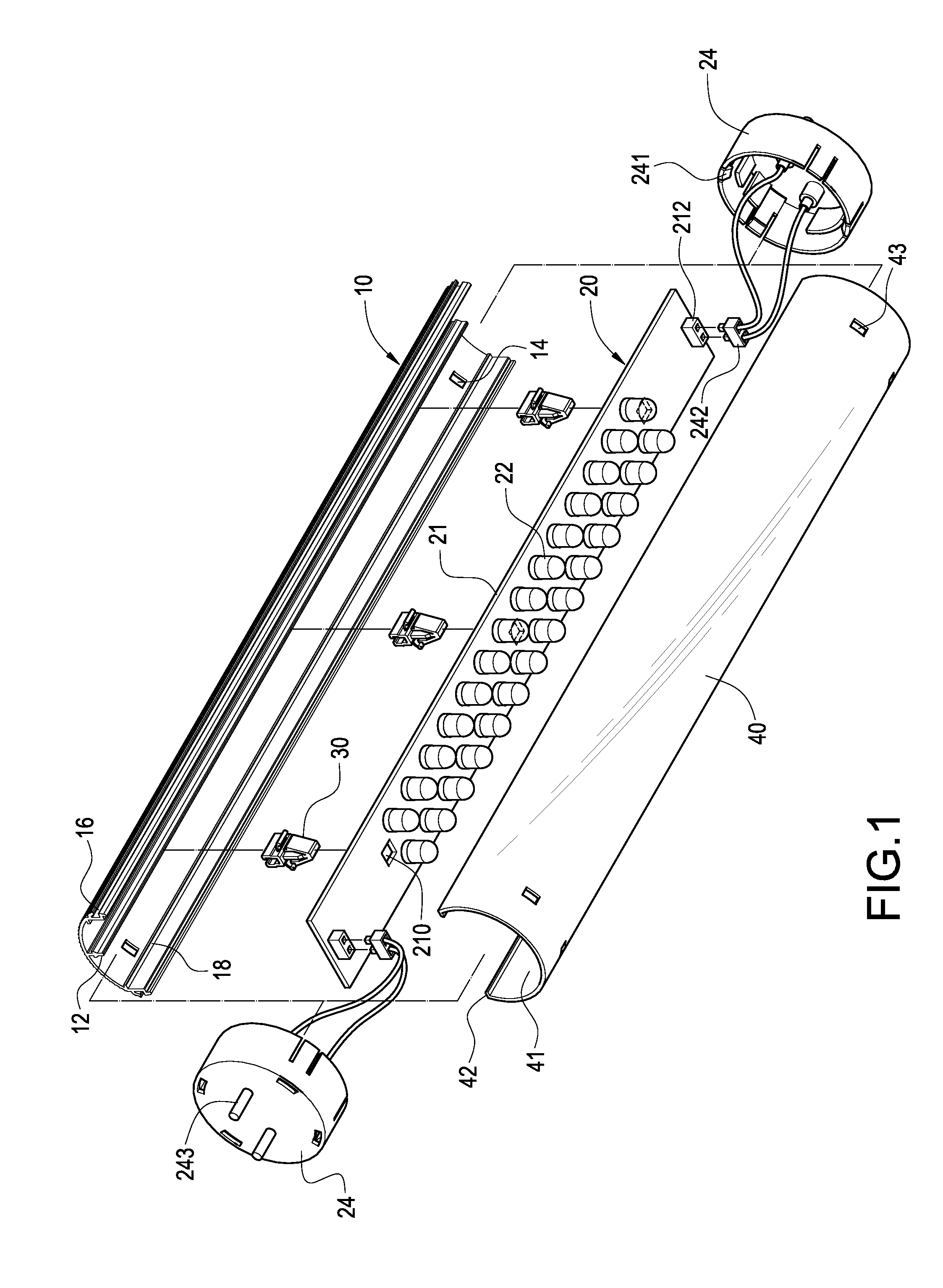
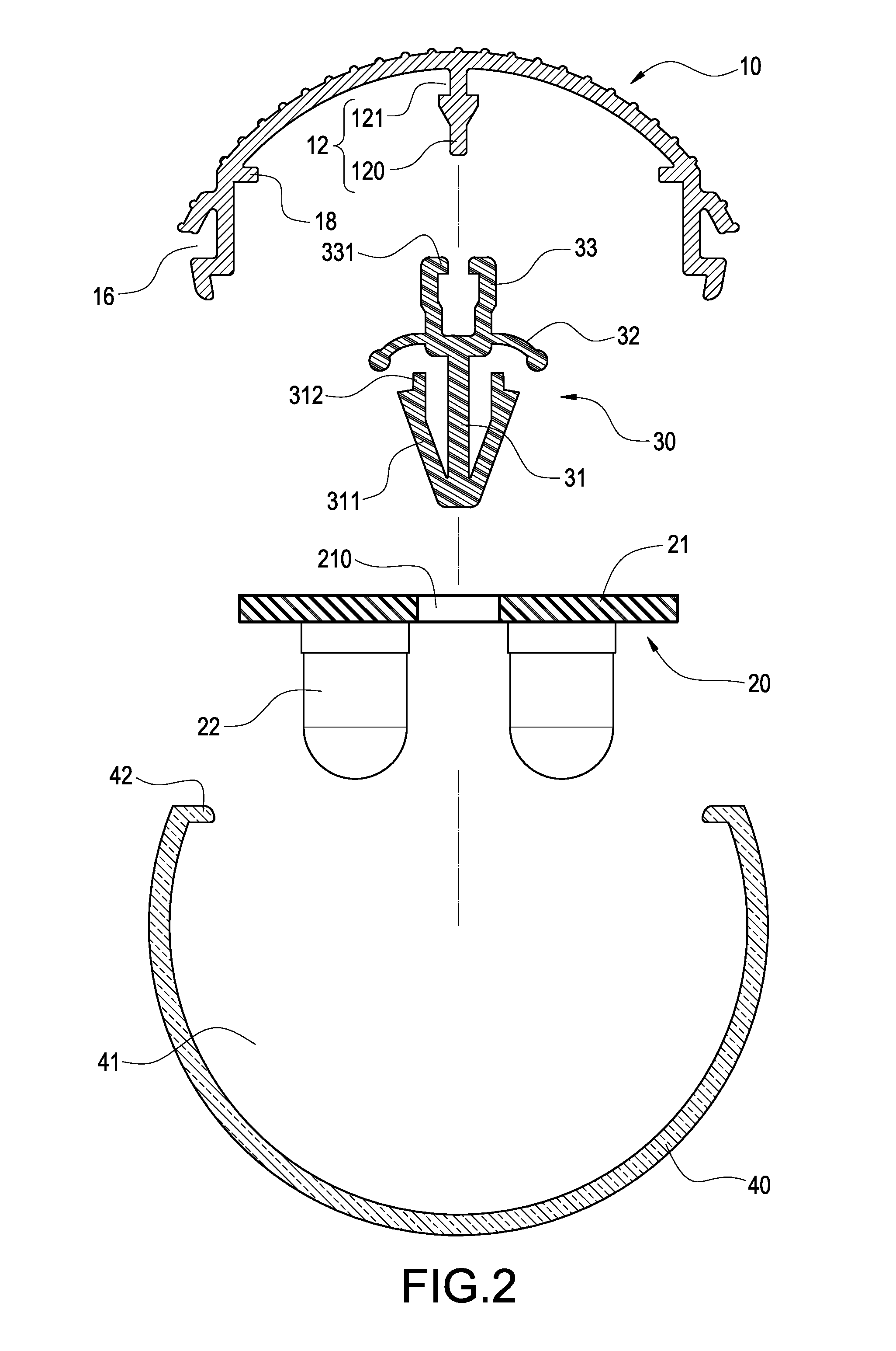
[0023]Please refer to FIG. 1, which is an exploded perspective view of the present invention. The present invention provides an assembly structure for a LED lamp, which includes a cover plate 10, a LED module 20, at least one fastener 30 and a mask 40.

[0024]The cover plate 10 is made of metals having high heat conductivity (such as aluminum) for protecting the LED module 20 and dissipating the heat thereof. The inner surface of the cover plate 10 extends to form a fixing portion 12 for allowing the fastener 30 to be fixed thereto. Both ends of the cover plate 10 are provided with a plurality of holes 14. Both sides of the cover plate 10 are formed with a slot 16 respectively.

[0025]The LED module 20 comprises a substrate 21 and a plurality of LED 22 mounted on th...


PUM


Abstract

An assembly structure for a LED lamp includes a cover plate, a LED module, fasteners and a mask. An inner surface of the cover plate is provided with a fixing portion. Both sides of the cover plate are formed with a slot respectively. The LED module has a substrate and a plurality of LED mounted on the substrate. The substrate is provided with an insertion hole. One end of the fastener is detachably connected into the insertion hole of the substrate and the other end thereof is fixed to the fixing portion. The mask is made of transparent materials and has an accommodating space for allowing the LED module to be disposed therein. Both sides of the mask defining the accommodating space are formed with a locking flange for inserting into the slot of the cover plate. With the above arrangement, the operator can assemble or detach the LED lamp quickly.

Description

BACKGROUND OF THE INVENTION[0001]1. Field of the Invention[0002]The present invention relates to a LED lamp, and in particular to an assembly structure for a LED lamp.[0003]2. Description of Prior Art[0004]Since light-emitting diodes (referred to as “LED” hereinafter) have advantages of low power consumption, long life, small volume and fast response time, they gradually replace traditional bulbs and are widely used in various lamps or light-emitting devices. In order to increase the illuminating range and brightness of such a lamp or light-emitting device, a plurality of LED is soldered with a circuit board to form a LED module. Then, the LED module is combined with a transparent mask and a metallic heat-dissipating cover. However, the transparent mask and the metallic heat-dissipating cover are made of different material, so that they usually need to be assembled together by screw elements.[0005]The conventional LED lamp includes a LED circuit board, a transparent mask, a metallic...

Claims


Application Information

Patent Timeline
Patent Type & Authority Applications(United States)
IPC IPC(8): F21V1/00F21S4/00
CPCF21K9/17F21S4/003F21V19/004F21V17/164F21Y2101/02F21Y2103/003F21V19/045F21S4/20F21K9/27F21Y2103/10F21Y2115/10F21K9/66F21V19/04
Inventor LIN, KUO-LENLIN, CHEN-HSIANGHUNG, MONG-HUAWANG, HWAI-MINGHSU, KENCHENG, CHIH-HUNG
Owner KITAGAWA HLDG
Why Eureka
Try Eureka