Vehicle occupant protection apparatus

a technology for occupant protection and vehicle, which is applied in the direction of pedestrian/occupant safety arrangement, process and machine control, instruments, etc., can solve the problems of delay in deployment of air bags, and delay in propagation time of air bags, so as to prevent a delay of deployment

Active Publication Date: 2011-02-17
TOYOTA JIDOSHA KK
View PDF7 Cites 9 Cited by
  • Summary
  • Abstract
  • Description
  • Claims
  • Application Information

AI Technical Summary

Benefits of technology

[0032]According to the aspect of the invention, it is possible to provide a vehicle occupant protection apparatus that is able to advance a timing at which protection means, such as an air-bag device, is activated as compared with that of the related art to thereby prevent a delay of deployment of the protection means.

Problems solved by technology

In accordance with this, deployment of the air bag also delays by the propagation time Δt.
For this reason, when the side air bag is deployed at the time of a side collision, there have been many cases in which deployment of the air bag delays.

Method used


Image

  • Vehicle occupant protection apparatus
  • Vehicle occupant protection apparatus
  • Vehicle occupant protection apparatus

Examples


first embodiment

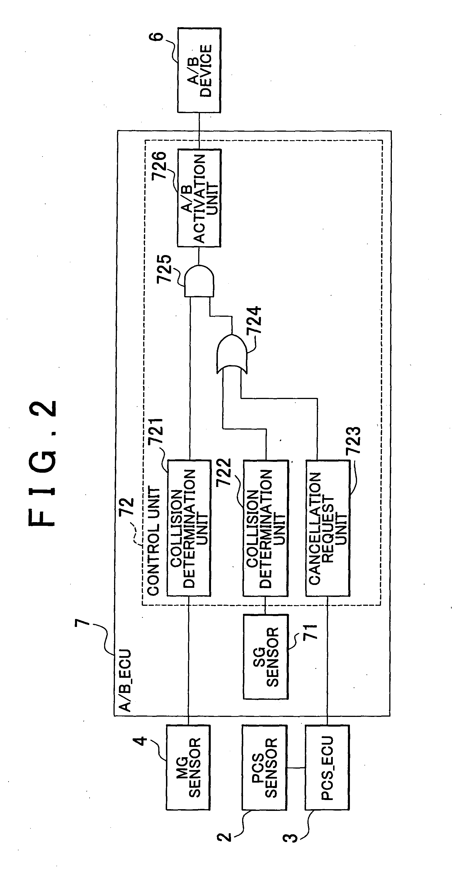
[0056]Next, the process flow of the control unit 72 in regard to the thus configured vehicle occupant protection apparatus will be described with reference to FIG. 3. FIG. 3 is a flowchart that shows the process flow of the control unit 72.

[0057]In FIG. 3, as the process starts, the processes of steps S10 to S12 are executed substantially at the same time. In step S10, the collision determination unit 721 regularly monitors the signal output from the MG sensor 4 and, when the collision determination unit 721 determines that a frontal collision has occurred (Yes in S10), outputs a signal that indicates the occurrence of the frontal collision to the AND gate 725. Note that when the collision determination unit 721 determines that no frontal collision is occurring, the process of step S10 is repeated. In step S11, the collision determination unit 722 regularly monitors the signal output from the SG sensor 71 and, when the collision determination unit 722 determines that a frontal coll...

second embodiment

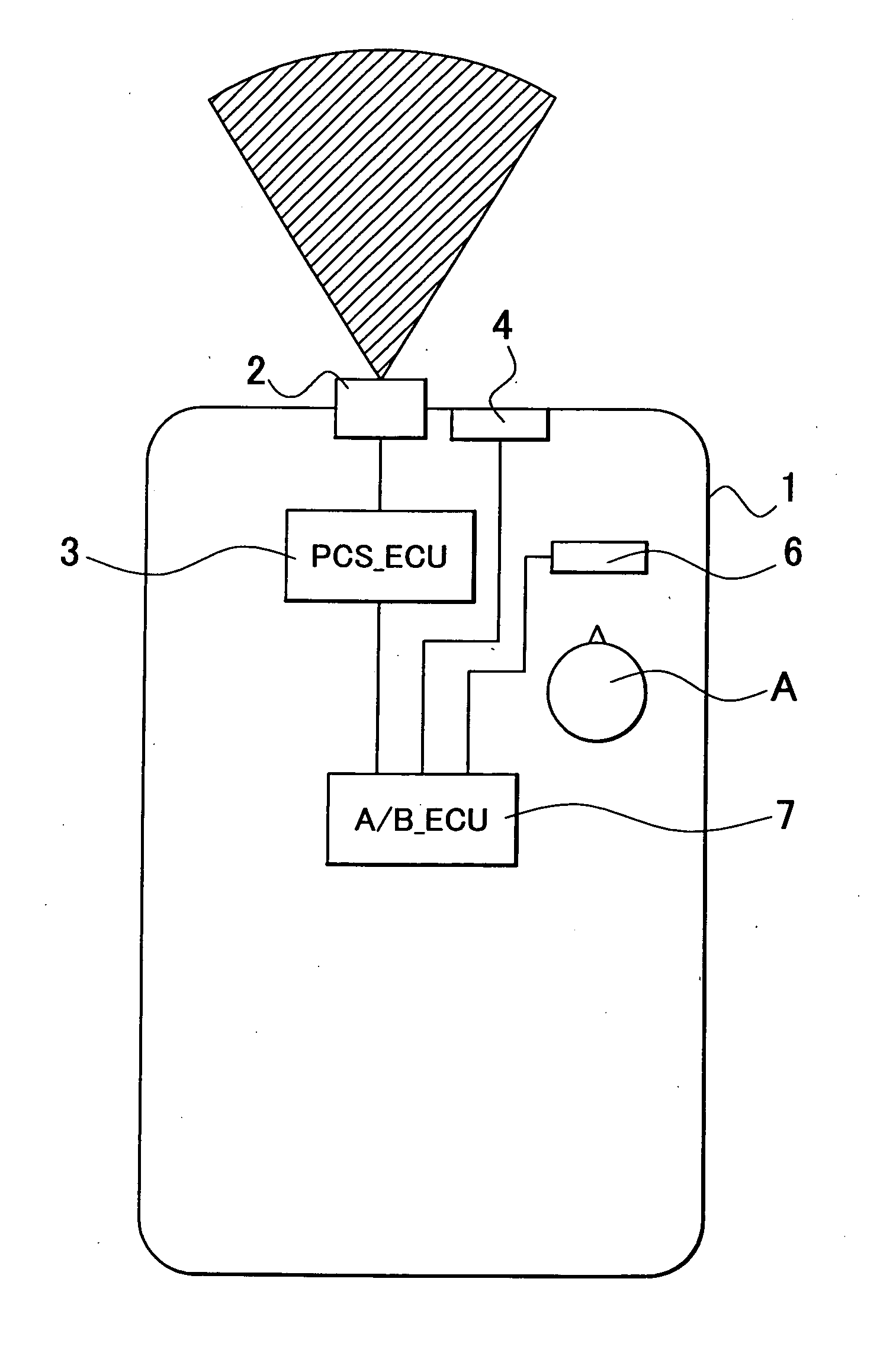
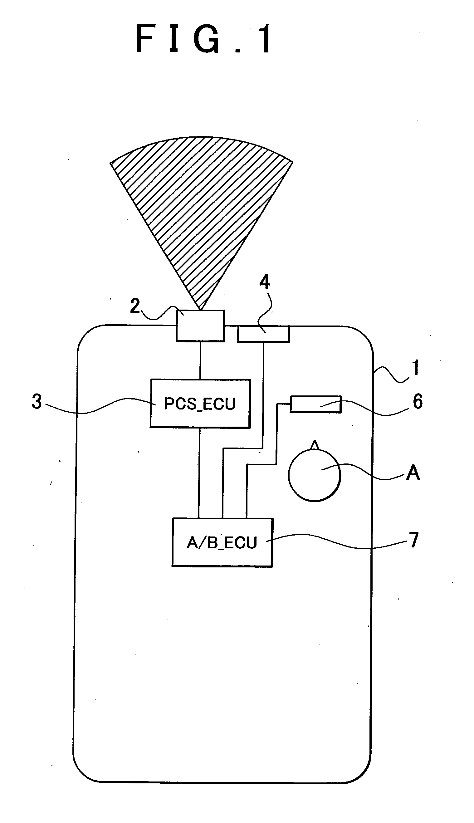
[0065]As shown in FIG. 6, the vehicle occupant protection apparatus is mounted on a vehicle 1, and includes a right PCS sensor 2a, a left PCS sensor 2b, a PCS_ECU 3, a right MG sensor 4a, a left MG sensor 4b, an A / B_ECU 9, a right A / B device 6a, and a left A / B device 6b.

[0066]The right PCS sensor 2a is formed of a radar and is mounted at the front right of the vehicle 1. The left PCS sensor 2b is formed of a radar and is mounted at the front left of the vehicle 1. The PCS_ECU 3 is mounted inside the vehicle 1. The PCS_ECU 3 estimates the course of a target vehicle on the basis of information acquired by the right PCS sensor 2a and the left PCS sensor 2b, and calculates the likelihood of a collision of the host vehicle on the basis of the estimated course of the target vehicle. When the likelihood of a collision of the host vehicle increases, and when the collision will occur at the right side of the vehicle1 (right-side collision), the PCS_ECU 3 predicts a right-side collision of ...


PUM


Abstract

A vehicle occupant protection apparatus includes a first collision detection mechanism provided for a vehicle and that detects a collision of the vehicle; a second collision detection mechanism provided closer to a middle of the vehicle than the first collision detection mechanism and that detects a collision of the vehicle; a first protection mechanism that protects an occupant from a collision of the vehicle; a controller that activates the first protection mechanism at the time when the first and second collision detection mechanisms detect a collision of the vehicle; and a collision prediction mechanism that predicts a collision of the vehicle. Every time the collision prediction mechanism predicts a collision of the vehicle in a direction from the first collision detection mechanism toward the middle of the vehicle, the controller activates the first protection mechanism at the time when the first collision detection mechanism detects the collision of the vehicle.

Description

BACKGROUND OF THE INVENTION[0001]1. Field of the Invention[0002]The invention relatesto a vehicle occupant protection apparatus and, more particularly, to a vehicle occupant protection apparatus, such as a vehicle air-bag system.[0003]2. Description of the Related Art[0004]A generally known air-bag system provides a technology for deploying an air bag at the time when a main G sensor and a safing G sensor both detect a collision of a vehicle in order to prevent erroneous deployment of the air bag. In regard to the above technology, in recent years, an air-bag system that is able to deploy an air bag even when an abnormal condition, such as a fault or a break, occurs in a safing G sensor, which is, for example, suggested in Japanese Patent Application Publication No. 2005-239059 (JP-A-2005-239059).[0005]Hereinafter, an air-bag system that is able to deploy an air bag even when an abnormal condition, such as a fault or a break, occurs in a safing G sensor according to a related art wi...

Claims


Application Information

Patent Timeline
Patent Type & Authority Applications(United States)
IPC IPC(8): B60R21/0132B60R21/00B60R21/0134B60R21/0136B60R21/02B60R21/16
CPCB60R21/0134B60R2021/0119B60R2021/01027
Inventor TSUNEKAWA, JUNIYODA, MOTOMI
Owner TOYOTA JIDOSHA KK
Why Eureka
Try Eureka