Auger stripper arrangement for corn head

a corn head and stripper technology, applied in the field of corn head, can solve the problems of stalling, operation failure, and affecting the harvesting of corn head, and achieve the effects of preventing the stalling of the rotating stalk roll, and preventing the stalling of the harvesting

Inactive Publication Date: 2011-02-24
ROTTINGHAUS DORIS L +1
View PDF45 Cites 26 Cited by
  • Summary
  • Abstract
  • Description
  • Claims
  • Application Information

AI Technical Summary

Benefits of technology

[0006]Accordingly, it is an object of the present invention to eliminate the use of vegetation-gathering chains in a corn head incorporated in a combine.
[0008]A further object of the present invention is to separate an ear of corn from a corn stalk by means of a combine corn head during harvesting in a reliable, efficient and effective manner without the use of vegetation-gathering chains in the corn head.
[0009]A still further object of the present invention is to increase the speed at which corn is harvested by a combine without reducing the corn recovery rate.
[0010]Yet another object of the present invention is to prevent crop residue from accumulating in a combine corn head during harvesting by improving the manner in which the corn stalks are separated from an ear of corn, are reduced to small pieces of vegetation, and are discharged form the combine.
[0011]Still another object of the prevent invention is to improve and facilitate the recovery of corn from down corn stalks lying on the ground during harvesting.
[0012]It is another object of the present invention to provide a corn head for use in a combine in the harvesting of corn which is easily adjusted to accommodate the processing of corn stalks having a wide range of diameters and conditions.

Problems solved by technology

Pieces of the broken gathering chains 12 tend to continue on a rearward path in the corn head 10 under the influence of the rotating stalk rolls and enter the combine causing damage or destruction to various combine components and resulting in operational failure.
The rotating stalk roll is also subject to plugging, or stalling, when dense weeds or wet stalks are ingested.
Any of the aforementioned interruptions in operation results in reduced productivity.

Method used


Image

  • Auger stripper arrangement for corn head
  • Auger stripper arrangement for corn head
  • Auger stripper arrangement for corn head

Examples


Embodiment Construction

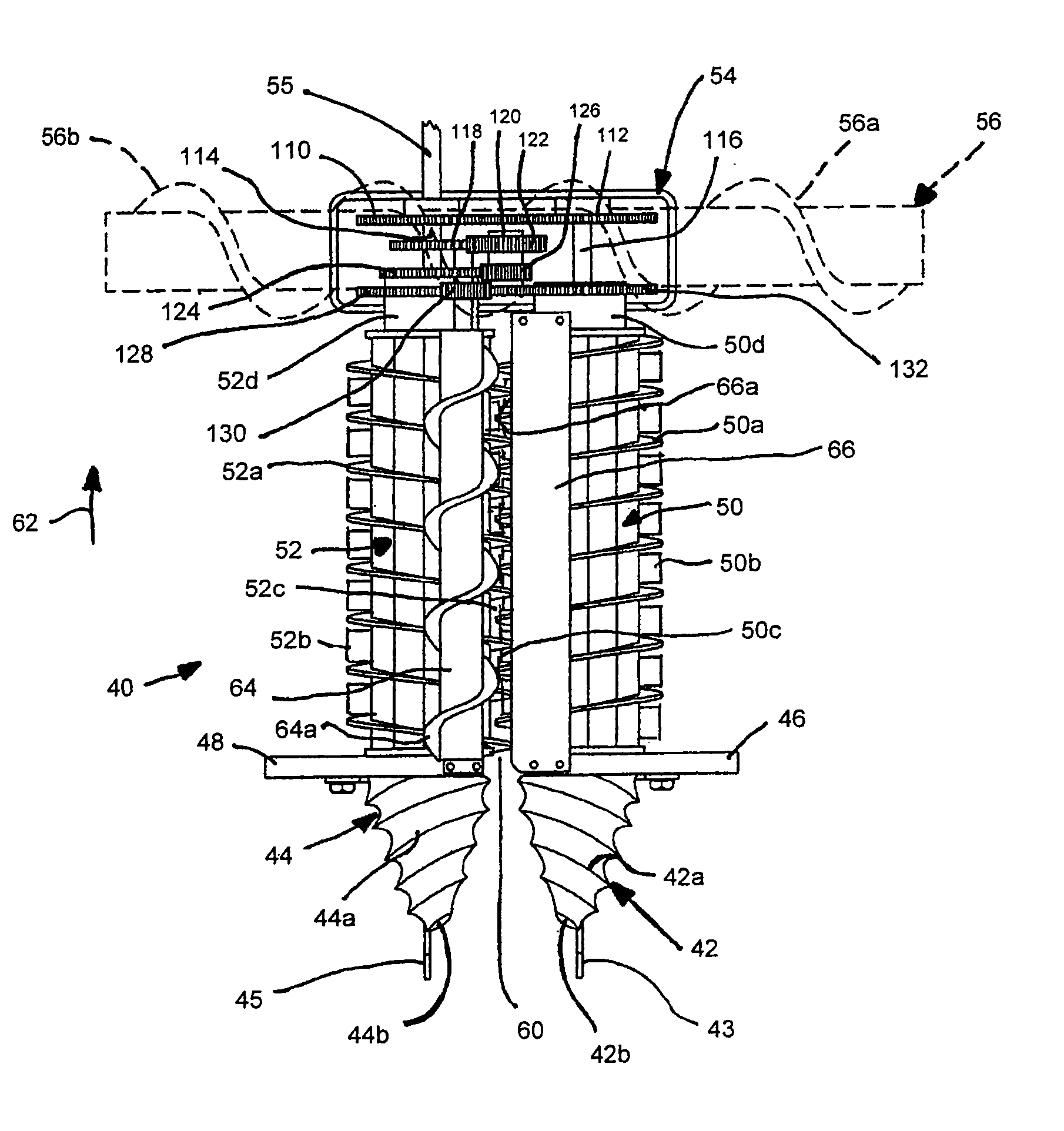
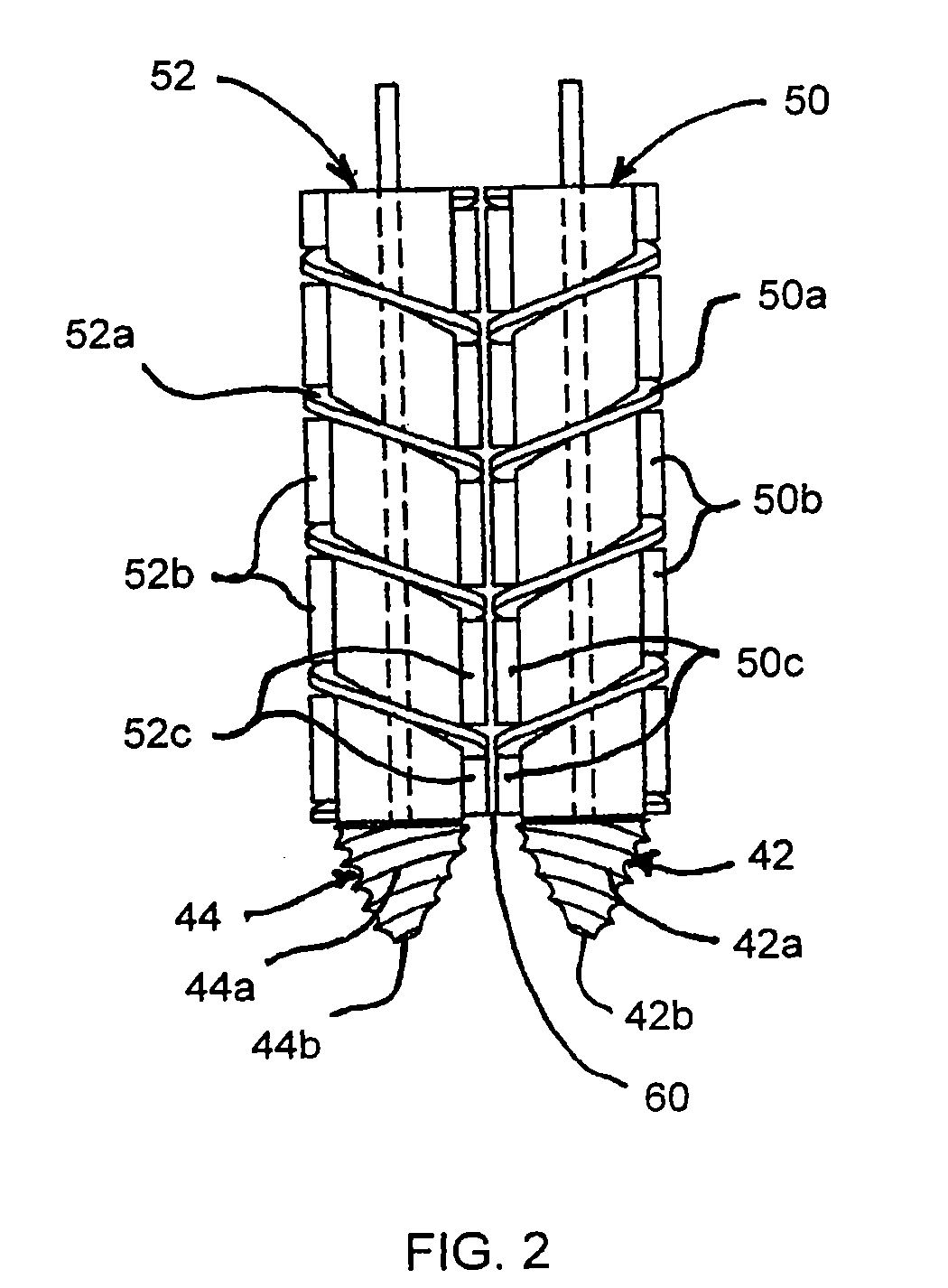
[0039]Referring to FIG. 2, there is shown a top plan view of a row unit 40 incorporating left and right pick-up cones 42 and 44 and left and right stalk rolls 50 and 52 in accordance with the present invention. FIG. 3 is a top plan view of the aforementioned combination of pick-up cones and stalk rolls as well as an auger 64 and a stripper plate 66, also in accordance with the present invention. FIG. 3a is a side elevation of the arrangement of FIG. 3 illustrating additional details of the inventive corn head installation on a combine.

[0040]The left and right pick-up cones 42, 44 include respective outer fluting 42a and 44a as well as respective generally pointed end portions 42b and 44b oriented in the direction of travel of the combine. The first and second pick-up cones 42, 44 are adapted for engaging and lifting corn stalks lying on the ground and directing these corn stalks into the combination of the first and second stalk rolls 50 and 52. The left and right pick-up cones 42, ...


PUM


Abstract

A corn head includes plural pairs of first and second laterally spaced rotating stalk rolls each having outer fluting and plural outer arrays of spaced knife members extending along the length of each stalk roll. Corn stalks are directed by rotating pick-up cones each disposed forward of a respective stalk roll into the space between adjacent stalk rolls, where the stalks are directed downwardly through the inter-roll space and are reduced by the cutting action of the rotating knives. Each pick-up cone and its associated stalk roll rotate in opposite directions as do the two stalk rolls. Disposed above and extending along the length of the stalk rolls are a closely spaced upper auger and stripper plate which remove an ear of corn from the stalk and direct the ear to the combine for further processing. A skid plate is disposed adjacent a lower, forward portion of each pick-up cone.

Description

CROSS REFERENCE TO RELATED APPLICATION[0001]This application is a continuation-in-part of U.S. patent application Ser. No. 12 / 544,922 filed on Aug. 20, 2009.FIELD OF THE INVENTION[0002]This invention relates generally to the harvesting of agricultural crops, and is particularly directed to a corn head as used with a combine in the harvesting of corn.BACKGROUND OF THE INVENTION[0003]Corn is generally harvested using a corn head 10 as shown in the perspective view of FIG. 1. The corn head 10 is attached to a forward, or leading, end of a combine (not shown in the figure for simplicity) which receives and processes the ears of corn from the corn head. A typical corn head as shown for the corn head 10 in FIG. 1 includes a left end 12 and a right end 14 with plural spaced row units 30 disposed therebetween. Row dividers 16 are displaced through a field such that the individual rows of corn are directed into the gaps 18 between adjacent row dividers which retrieve, lift and direct the row...

Claims


Application Information

Patent Timeline
Patent Type & Authority Applications(United States)
IPC IPC(8): A01D45/02
CPCA01D45/021
Inventor ROTTINGHAUS, ROBERT
Owner ROTTINGHAUS DORIS L
Why Eureka
Try Eureka