Heat dissipation module

Inactive Publication Date: 2011-02-24
HON HAI PRECISION IND CO LTD
View PDF31 Cites 6 Cited by
  • Summary
  • Abstract
  • Description
  • Claims
  • Application Information

AI Technical Summary

Problems solved by technology

These added electronic components will interfere with the

Method used


Image

  • Heat dissipation module
  • Heat dissipation module
  • Heat dissipation module

Examples


Embodiment Construction

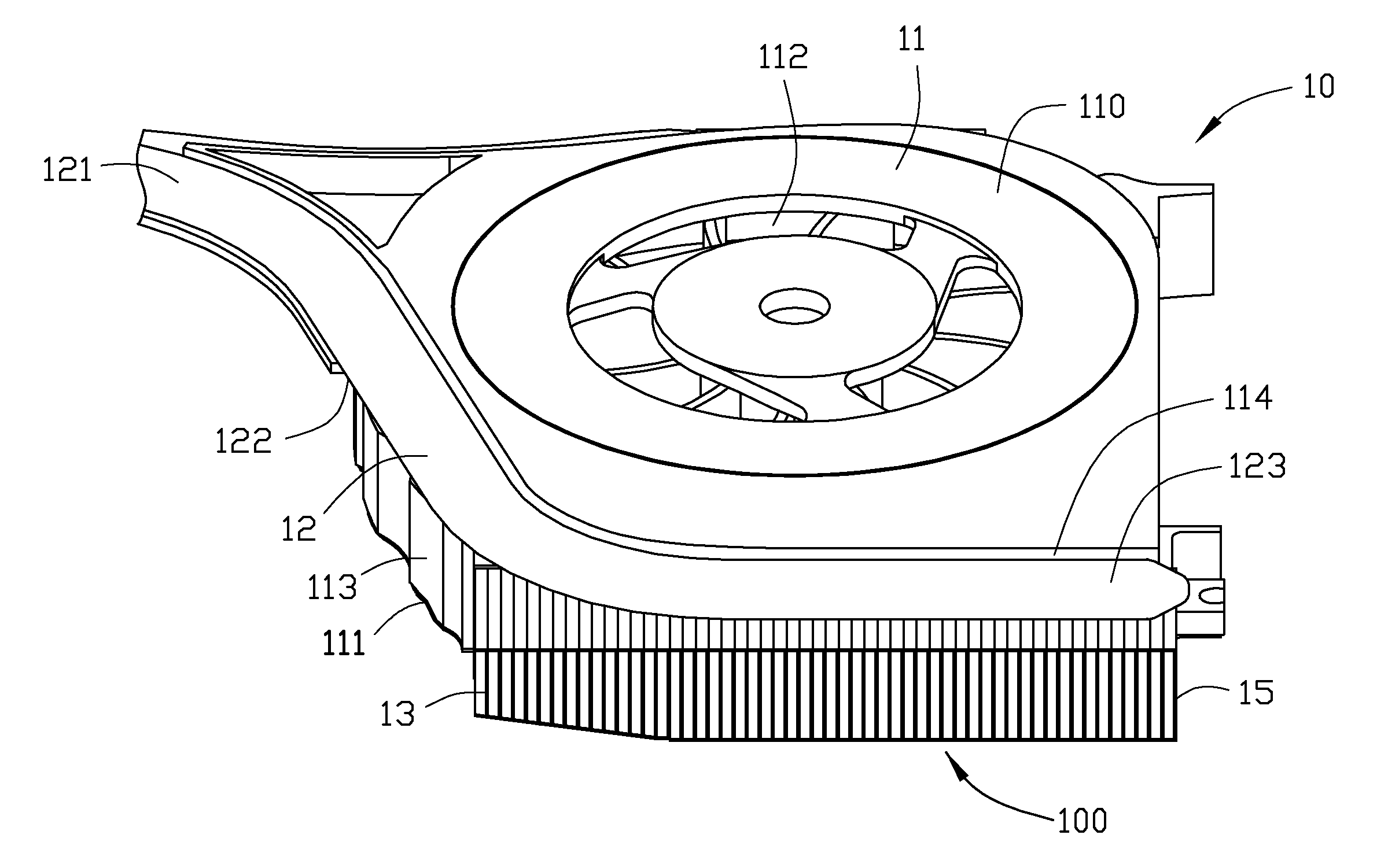
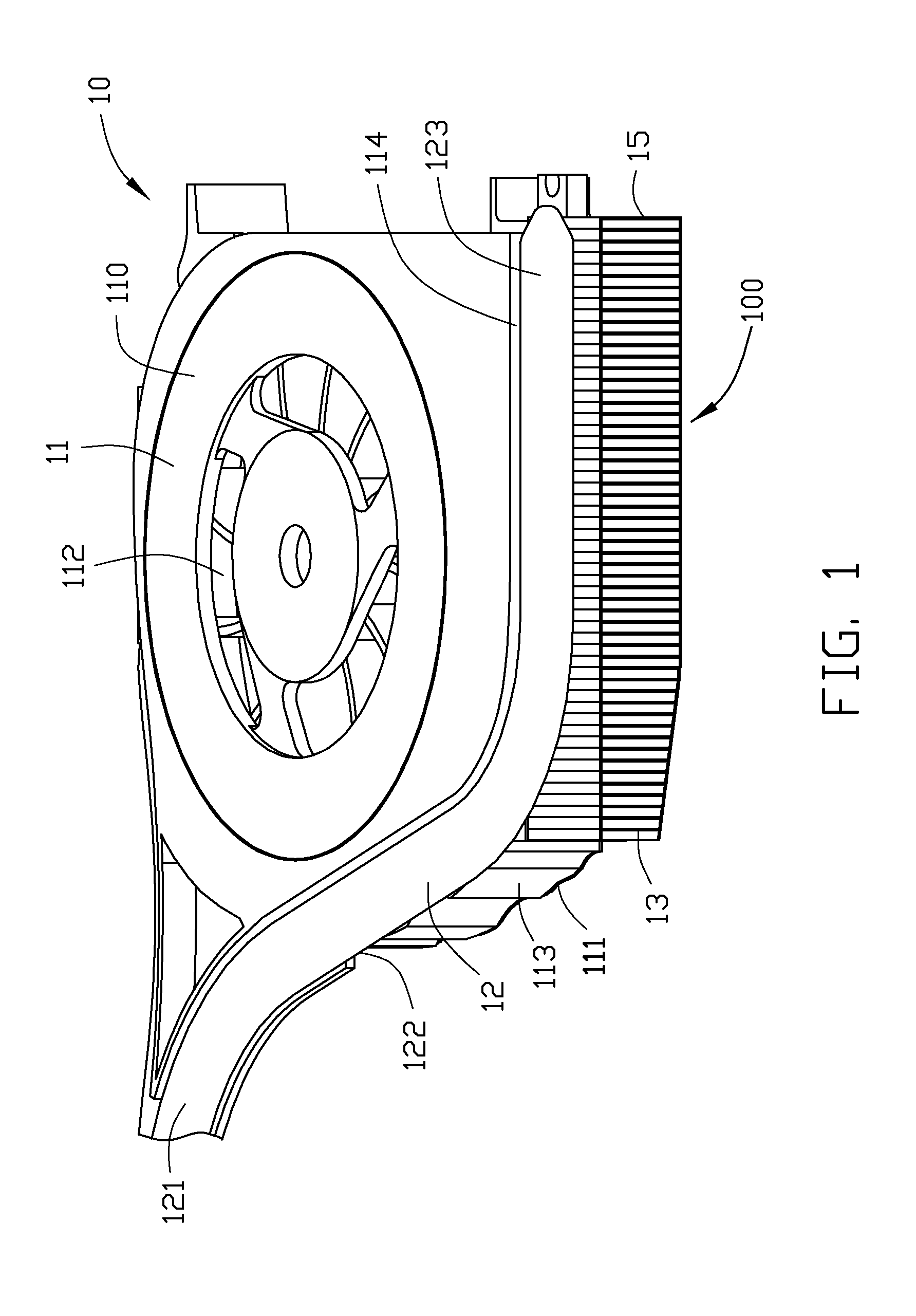
FIG. 1 shows a heat dissipation module 10 in accordance with a first embodiment of the present disclosure. The heat dissipation module 10 includes a centrifugal fan 11, a heat pipe 12, and a fin assembly 100. The heat dissipation module 10 is particularly suitable for use in a notebook computer for dissipating heat of heat-generating electronic components of the notebook computer.

The centrifugal fan 11 includes a top plate 110, a bottom plate 111 and a sidewall 113 interconnecting the top plate 110 with the bottom plate 111. The centrifugal fan 11 defines an air inlet 112 at the top plate 110 and an air outlet 114 at the sidewall 113, wherein the air outlet 114 is perpendicular to the air inlet 112. The heat pipe 12 is flat, including a planar top surface 121 and a planar bottom surface 122. The heat pipe 12 includes an evaporating section for absorbing heat from an electronic component of the notebook computer, and a condensing section 123 located at a top side of the air outlet 11...


PUM


Abstract

A heat dissipation module includes a heat pipe having a condensing section, a centrifugal fan defining an air outlet and a fin assembly. The fin assembly includes a plurality of fins stacked together and is thermally attached to the condensing section of the heat pipe. The fin assembly is located at the air outlet of the centrifugal fan. At least some fins of the fin assembly have a height decreasing along the condensing section of the heat pipe. The fin assembly defines a spared space at a bottom side of the fin assembly corresponding to the at least some fins.

Description

BACKGROUND1. Technical FieldThe present disclosure relates to heat dissipation modules, and particularly to a heat dissipation module for use in a notebook computer to dissipate heat generated by heat-generating electronic components of the notebook computer.2. Description of Related ArtWith continuing development of notebook computer technology, heat-generating electronic components such as CPUs (central processing units) are generating more and more heat which requires immediate dissipation. Generally, heat dissipation modules are attached to the electronic components to provide such heat dissipation. A conventional heat dissipation module includes a fin assembly, a heat pipe and a centrifugal fan. The heat pipe connects the electronic component with the fin assembly to transfer heat from the electronic component to the fin assembly. The centrifugal fan defines an air outlet facing the fin assembly to provide a forced airflow to cool the fin assembly. However, the notebook compute...

Claims


Application Information

Patent Timeline
IPC IPC(8): F28D15/04G06F1/20F28D21/00F28F7/00
CPCF28D1/0226F28D15/0266F28F2215/04G06F1/203F28F1/12
Inventor CHEN, RUNG-AN
Owner HON HAI PRECISION IND CO LTD
Why Eureka
Try Eureka