Pumping module and system

a technology of pumping module and pumping system, which is applied in the direction of underwater drilling, drilling machines and methods, and well accessories, etc., can solve the problems of increasing the complexity of the operation which has to be performed, the difficulty of achieving the effect of reducing the fraction of free gas, increasing the flow produced, and increasing the fluid energy

Active Publication Date: 2011-02-24
PETROLEO BRASILEIRO SA (PETROBRAS)
View PDF21 Cites 6 Cited by
  • Summary
  • Abstract
  • Description
  • Claims
  • Application Information

AI Technical Summary

Benefits of technology

[0118]Preferably, in these embodiments, when oil is pumped in from the production well (P) the well pump (13) increases the energy of the fluid in the form of pressure and transmits this increase in energy in the form of an increase in suction pressure to the second pump (8) of the subsea module (PM) which as a consequence reduces the fraction of free gas, increasing the flow produced.

Problems solved by technology

Prospecting and production from wells in fields producing hydrocarbons located in increasingly deep water is accompanied by technical difficulties and an increase in the complexity of the operations which have to be performed.
The higher the gas fraction, the greater the difficulty encountered in pumping operations, as the presence of gas is prejudicial to pump performance, and sometimes rules out the use of this method of lifting.
In addition to increasing costs, this proposal does not appear to be very efficient, given that as the gas is separated off and removed lifting energy associated with that gas is also removed, and this directly implies the use of high-powered pumps and a very great increase in pressure, especially in the case of deep water.
The disadvantage of this method, mainly in the case of subsea completion (subsea wells), is the great concentration of equipment within the production well, which if a fault should occur requires long-term action on the well (tens of days) in order to make a repair, and this involves removal the column, which requires a very expensive rig.
Nevertheless, because of the substantially vertical geometry of the module, which is tens of metres in length, there is also a greater possibility that a retention space will form and block gas at its top, adversely affecting pump suction.
Conversely, the slender geometry of this type of pump gives rise to parallel development of solutions for their accommodation, as already mentioned above, and the main restriction on the installation of these pumps outside a production well is their low tolerance to flows of fluid with high fractions in terms of gas.

Method used


Image

  • Pumping module and system
  • Pumping module and system
  • Pumping module and system

Examples


first embodiment

[0146]A subsea pumping system for the production of hydrocarbons with a high gas fraction, another aspect of this invention, can be seen in the first embodiment in FIG. 3. It may comprise any of the embodiments already mentioned for the pumping module (PM) installed on the sea bed, preferably alongside an oil production well.

[0147]It will be noted that the illustrated system comprises:[0148]a first transport pipe (T1) which links the SPU with the annulus of the production well (P) to deliver drive fluid to a well pump (13) installed at the bottom of a production well (P) draining a reservoir (R),[0149]a second transport pipe (T2) connecting the outlet of well pump (13) via a hydraulic connector (10) to the oil inlet pipe (2) of the pumping module (PM),[0150]a third transport pipe (T3) connecting outlet pipe (9) from the pumping module (PM) to the SPU.

second embodiment

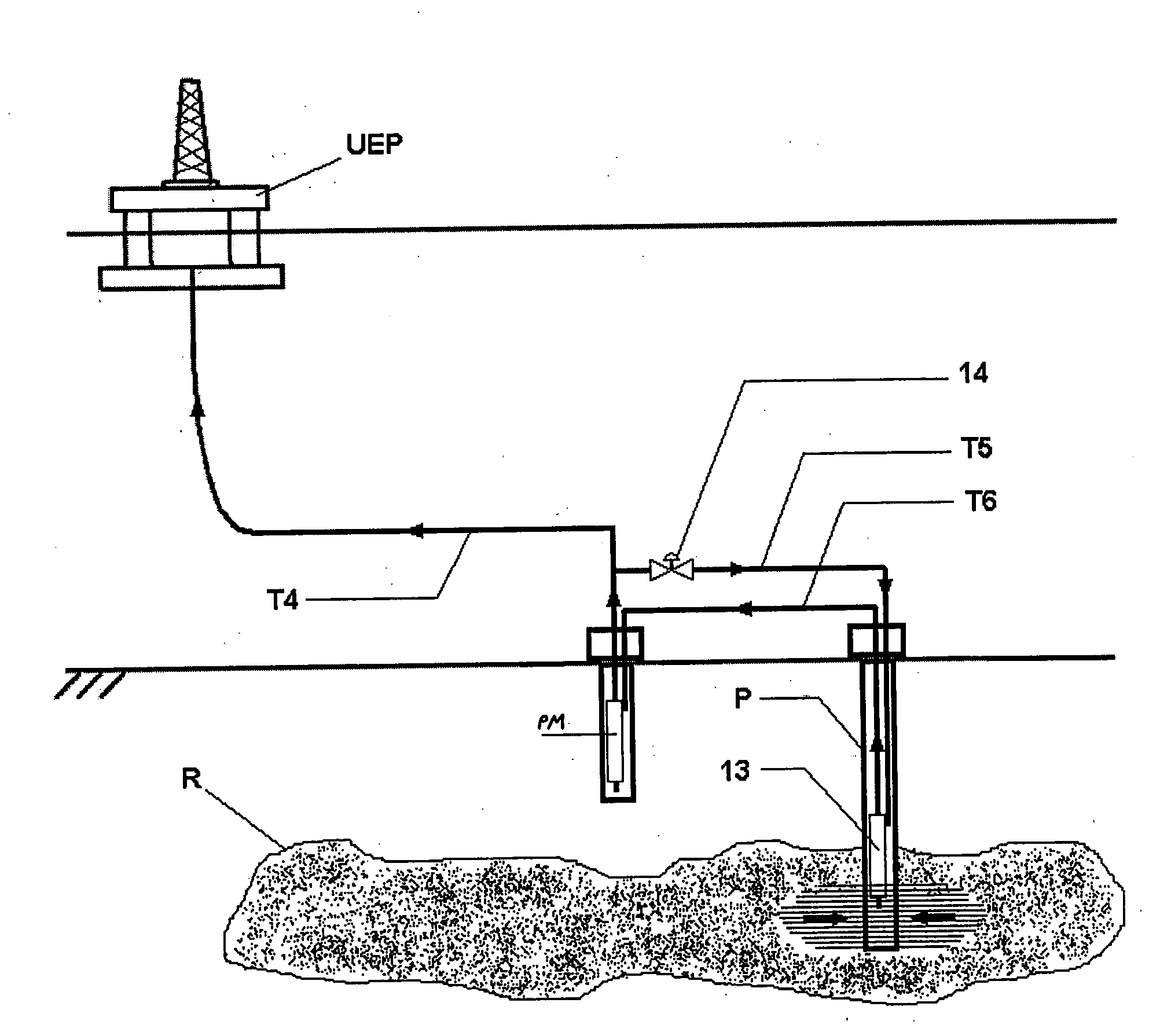
[0151]The subsea pumping system for the production of hydrocarbons having a high gas fraction according to this invention can be seen in a second embodiment in FIG. 4 which again may comprise any of the embodiments already mentioned for the pumping module (PM) installed on the sea bed, again preferably alongside an oil production well.

[0152]It will be noted that this system comprises:[0153]a first transport pipe (T4) connecting outlet pipe (9) from the pumping module (PM) to the SPU,[0154]a second transport pipe (T5) connecting the pumping module (PM) via the annular space of the production well (P) to the well pump (13) for the supply of drive fluid,[0155]a flow valve (14) located in the second transport pipe (T5) used to regulate the quantity of fluid pumped by the pumping module (PM) to the first transport pipe (T4) is diverted to a second transport pipe (T5) to act as drive fluid for well pump (13),[0156]a third transport pipe (T6) connecting the outlet from well pump (13) to th...


PUM


Abstract

This invention relates to equipment and a subsea pumping system using a subsea module installed on the sea bed, preferably away from a production well and intended to pump hydrocarbons having a high associated gas fraction produced by one or more subsea production wells to the surface. One object of this invention is achieved by means of the design of a pumping module (PM) which is linked to pumping equipment already present in a production well and which basically comprises: an inlet pipe (2), separator equipment (3), a first pump (4) and a second pump (8). In the subsea pumping system for the production of hydrocarbons with a high gas fraction, the other object of this invention, when oil is pumped from the production well (P) the well pump (13) increases the energy of the fluid in the form of pressure and transmits this increase in energy in the form of an increase in suction pressure in the second pump (8) of the subsea module (PM).

Description

FIELD OF THE INVENTION[0001]The present invention is related to subsea equipment and pumping systems, more particularly subsea modules located on the sea bed, preferably away from the production well and designed to pump to the surface hydrocarbons with a high associated gas fraction that is produced by one or more subsea production wells.STATE OF THE ART[0002]Prospecting and production from wells in fields producing hydrocarbons located in increasingly deep water is accompanied by technical difficulties and an increase in the complexity of the operations which have to be performed.[0003]Production of hydrocarbons in the high seas requires that production and injection wells be drilled beneath the sea and that subsea equipment must also be installed. Many of these wells produce hydrocarbons in the form of liquid and gas. The higher the gas fraction, the greater the difficulty encountered in pumping operations, as the presence of gas is prejudicial to pump performance, and sometimes ...

Claims


Application Information

Patent Timeline
Patent Type & Authority Applications(United States)
IPC IPC(8): E21B43/01E21B43/36E21B43/00
CPCE21B43/124E21B43/36E21B43/129
Inventor RODRIGUES, ROBERTO
Owner PETROLEO BRASILEIRO SA (PETROBRAS)
Why Eureka
Try Eureka