Electric stapler

a stapler and electric technology, applied in the field of electric staplers, can solve the problems of large current load, large noise generated when electric staplers are in operation, and large vertical load of current necessary to drive the heavy movable portion in the vertical direction, so as to reduce the operation weight and ensure the effect of stable paper binding

Active Publication Date: 2011-02-24
MAX CO LTD
View PDF9 Cites 3 Cited by
  • Summary
  • Abstract
  • Description
  • Claims
  • Application Information

AI Technical Summary

Benefits of technology

[0010]One or more embodiments of the invention provide an electric stapler, in which a part movable up and down for clamping sheets of paper is reduced in size to reduce an operation weight thereof, whereby, even when a binding space is set large, a stable paper binding can always be secured.

Problems solved by technology

In this case, in a structure in which the whole of the driver unit is moved down using a separate mechanism, an apparatus having such structure becomes large in size.
Thus, the load of a current necessary for driving the heavy movable portion greatly in the vertical direction is inevitably large and noises generated when the electric stapler is in operation also become loud accordingly.
Also, when the considerable heavy movable portion moves up and down suddenly, the connected portions of the connected staples within the staple storage portion can be separated from each other due to vibrations caused by the sudden vertical movement of the movable portion, and a feed pawl for supplying the connected staples to the strike-out portion can be caused to come off due to the bouncing movements of the connected staples, thereby raising a possibility that poor staple feed can occur.
Further, as the staples are consumed or new staples are supplied, the number of staples contained within the staple storage portion decreases or increases, whereby the weight of the staple storage portion decreases or increases.
In addition to this, when the stroke of the moving portion in the vertical movement thereof is large and also the staple storage portion bounces, the binding positions of the staples are caused to vary, thereby raising a possibility that the binding of the papers by the staples can be unstable.

Method used


Image

  • Electric stapler
  • Electric stapler
  • Electric stapler

Examples


Embodiment Construction

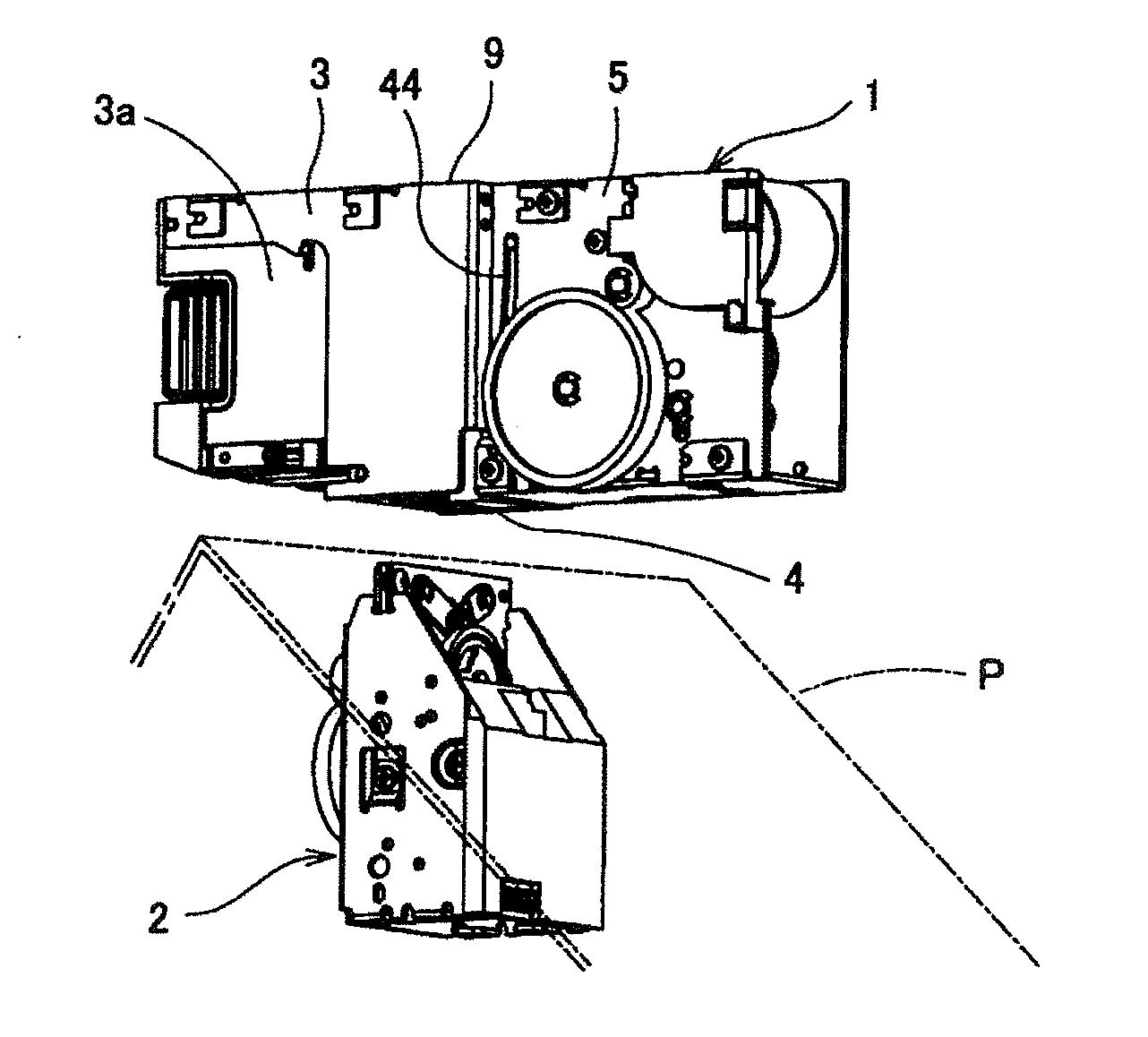
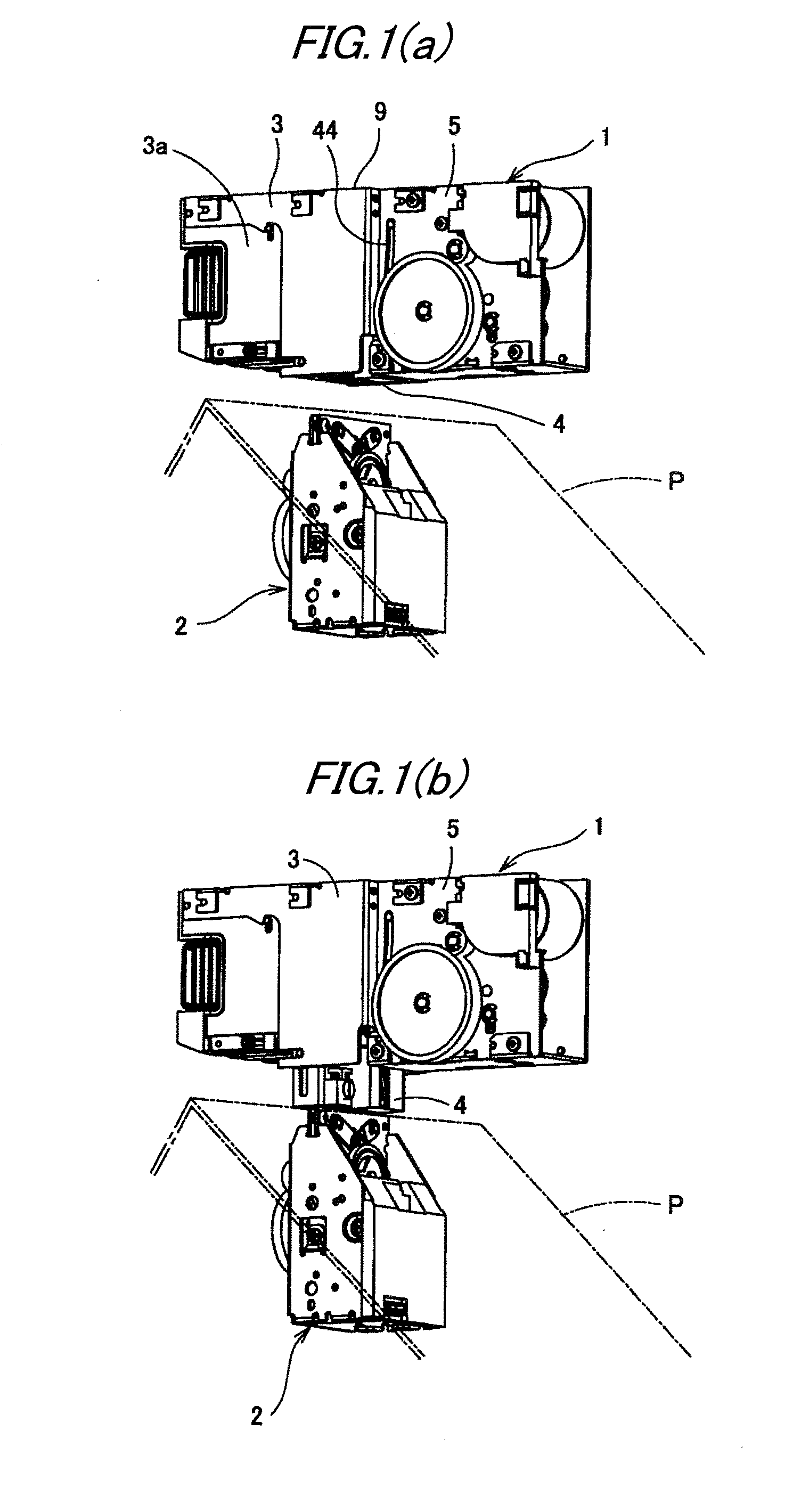
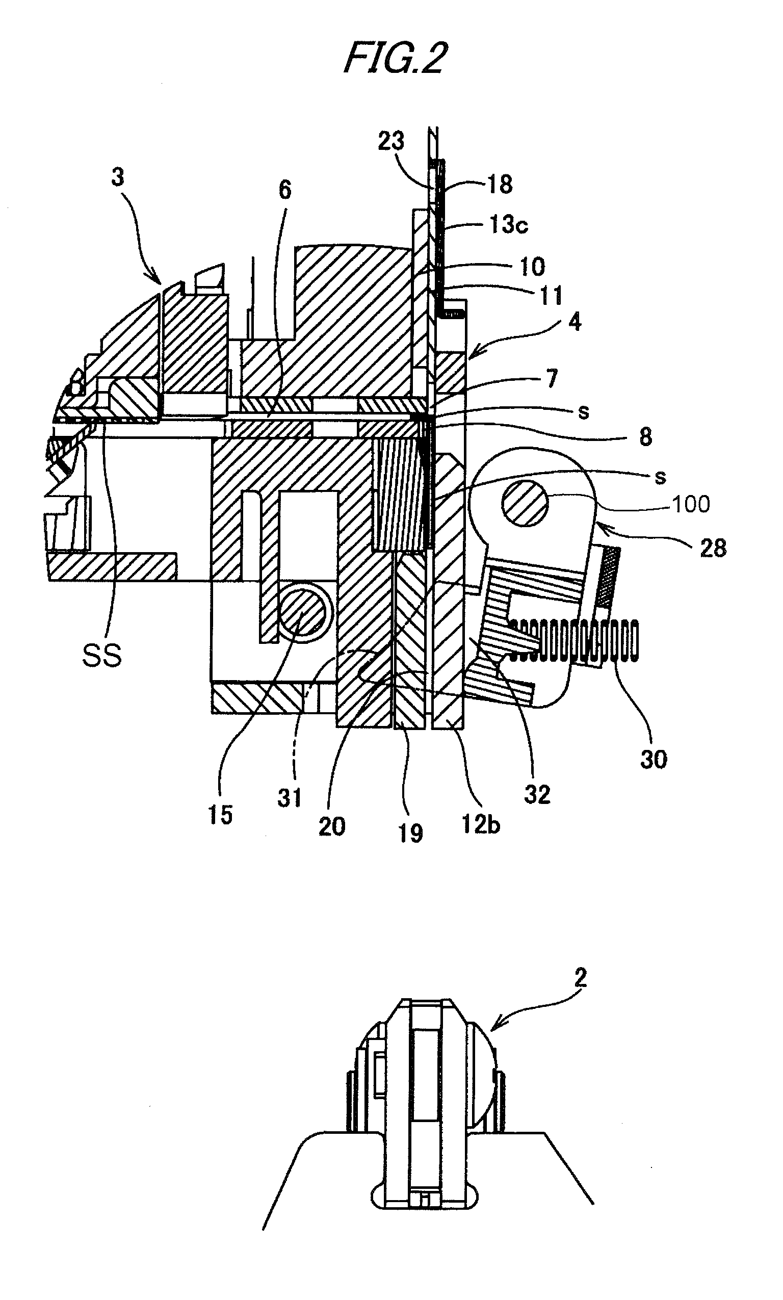
[0043]A vertically separated type saddle stitching stapler according to an exemplary embodiment of the invention is described with reference to FIGS. 1(a), 1(b) and 2.

[0044]As shown in FIGS. 1(a) and 1(b), the stapler of a vertically separated type includes a driver unit 1 and a clincher unit 2 which are separated from each other in the vertical direction, while papers P supplied to between the driver unit 1 and clincher unit 2 can be bound with a staple.

[0045]The driver unit 1 includes a staple storage portion 3 for storing a large number of connected staples, a head portion 4 for striking out staples, and a drive portion 5 for driving a driver which is slidably provided in the head portion 4. The clincher unit 2 includes a movable clincher for bending a staple struck out by the driver and a drive mechanism for driving the movable clincher.

[0046]In the staple storage portion 3 of the driver unit 1, there is stored a staple cartridge 3a. In the staple cartridge 3a, for example, ther...


PUM


Abstract

An electric stapler is provided with: a driver unit including a driver for striking out a staple to be penetrated through sheets of paper; and a clincher unit including a clincher for bending leg portions of the staple penetrated through the sheets of paper. The driver unit is provided with: a staple storage portion for storing therein a large number of connected staples; a head portion for striking out the staple; a drive portion configured to drive said driver provided slidably in the head portion; and a head raise/lower mechanism configured to relatively move the head portion with respect to the staple storage portion toward the clincher unit to thereby clamp the sheets of paper.

Description

BACKGROUND OF THE INVENTION[0001]1. Field of the Invention[0002]The present invention relates to an electric stapler provided with a driver unit including a driver for striking out a staple to bind sheets of paper and a clincher unit including a clincher for bending the staple struck out and penetrated through the sheets of paper.[0003]2. Related Art[0004]Patent reference 1 and Patent Reference 2 disclose vertically separated type saddle stitching staplers in which centers of paper bundles are bound. In an operation using these staplers, a central portion of the sheets of paper are bent, the portion are thereafter inserted into a binding space between a driver unit and a clincher unit, then the sheets of paper are bound. Since the bent portions of the centers of the sheets of paper are stacked in a manner that the centers direct upward, it is general to dispose the driver unit in an upper side and the clincher unit in a lower side. However, in this structure, since the stacking heig...

Claims


Application Information

Patent Timeline
Patent Type & Authority Applications(United States)
IPC IPC(8): B27F7/19
CPCB42B4/00B27F7/21
Inventor SUGIHARA, SHINPEIYAGI, NOBUAKI
Owner MAX CO LTD
Why Eureka
Try Eureka