
Methods for detecting failure states in a medicine delivery device

a failure state and medicine technology, applied in the field of medicine delivery devices, can solve the problems of high device cost, inability to detect failure states, and expensive scenarios, and achieve the effect of avoiding failure or malfunction of one componen

Active Publication Date: 2011-02-24
CEQUR SA
View PDF100 Cites 45 Cited by
  • Summary
  • Abstract
  • Description
  • Claims
  • Application Information

AI Technical Summary

Benefits of technology

The invention is a medicament infusion device that uses low-cost components that can be replaced periodically without having to dispose of other expensive components in the device. The device includes a patient attachment unit and an indicator unit that can be detachably coupled together. The patient attachment unit includes a housing and a flexible member, and the indicator unit includes a sensing module, a status determination module, and a notification module. The sensing module senses the pressure and flow rate of the fluid medicament, and the notification module notifies the patient of the status. The device can be attached to the skin surface of the patient, and the indicator unit can be detached and replaced without having to dispose of other expensive components in the device.

Problems solved by technology

While these devices are useful, they do suffer from several shortcomings.
First, the high expense of the devices makes them accessible to fewer people than the diabetic population members who may benefit from their use.
Second, failure or malfunction of one component requires repair or replacement of the entire device, a costly scenario.
For example, if the pump fails, often the entire unit (including the properly functioning—and expensive—electronics) must be replaced.
Third, over time the device gets dirty due to repeated uses, which requires periodic cleaning and may cause a failure condition at a later date.
Fourth, the complexity of the devices requires significant battery power to operate pumps, monitor sensors, and send alerts and notifications to a patient.
Power and electronic requirements are often so significant as to excessively require large batteries, thus increasing the physical size and cost of the device.

Method used


Image

  • Methods for detecting failure states in a medicine delivery device
  • Methods for detecting failure states in a medicine delivery device
  • Methods for detecting failure states in a medicine delivery device

Examples


Embodiment Construction

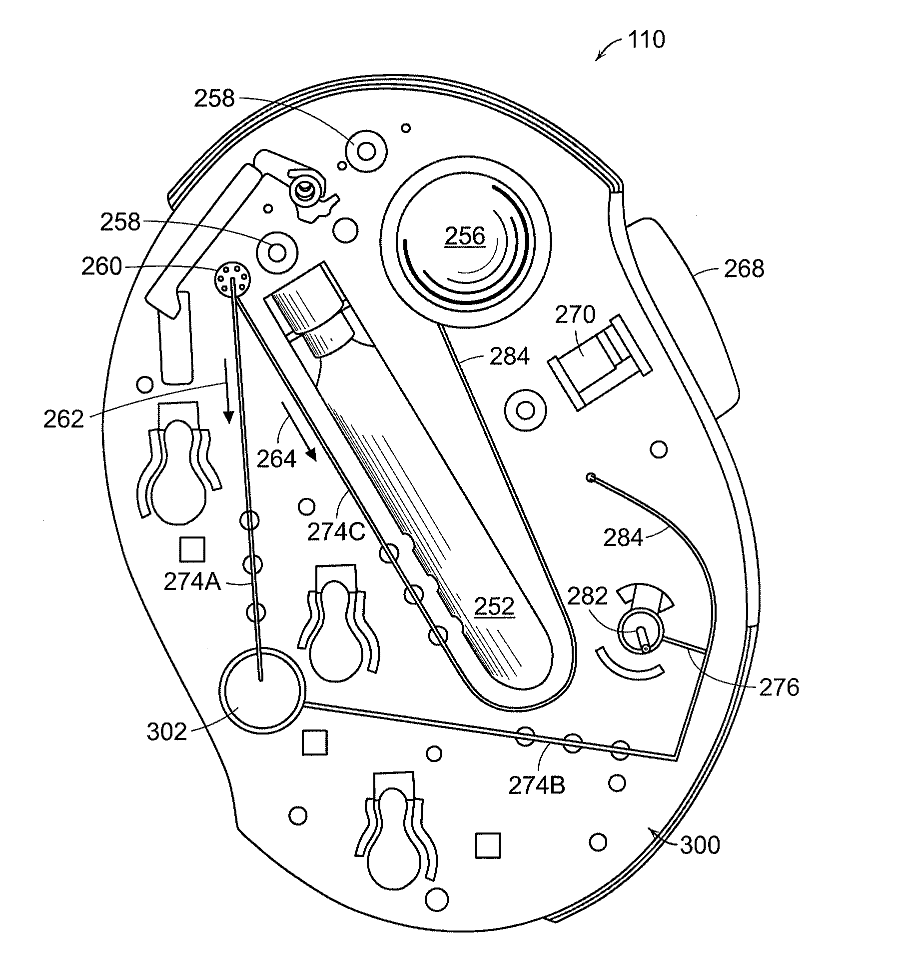
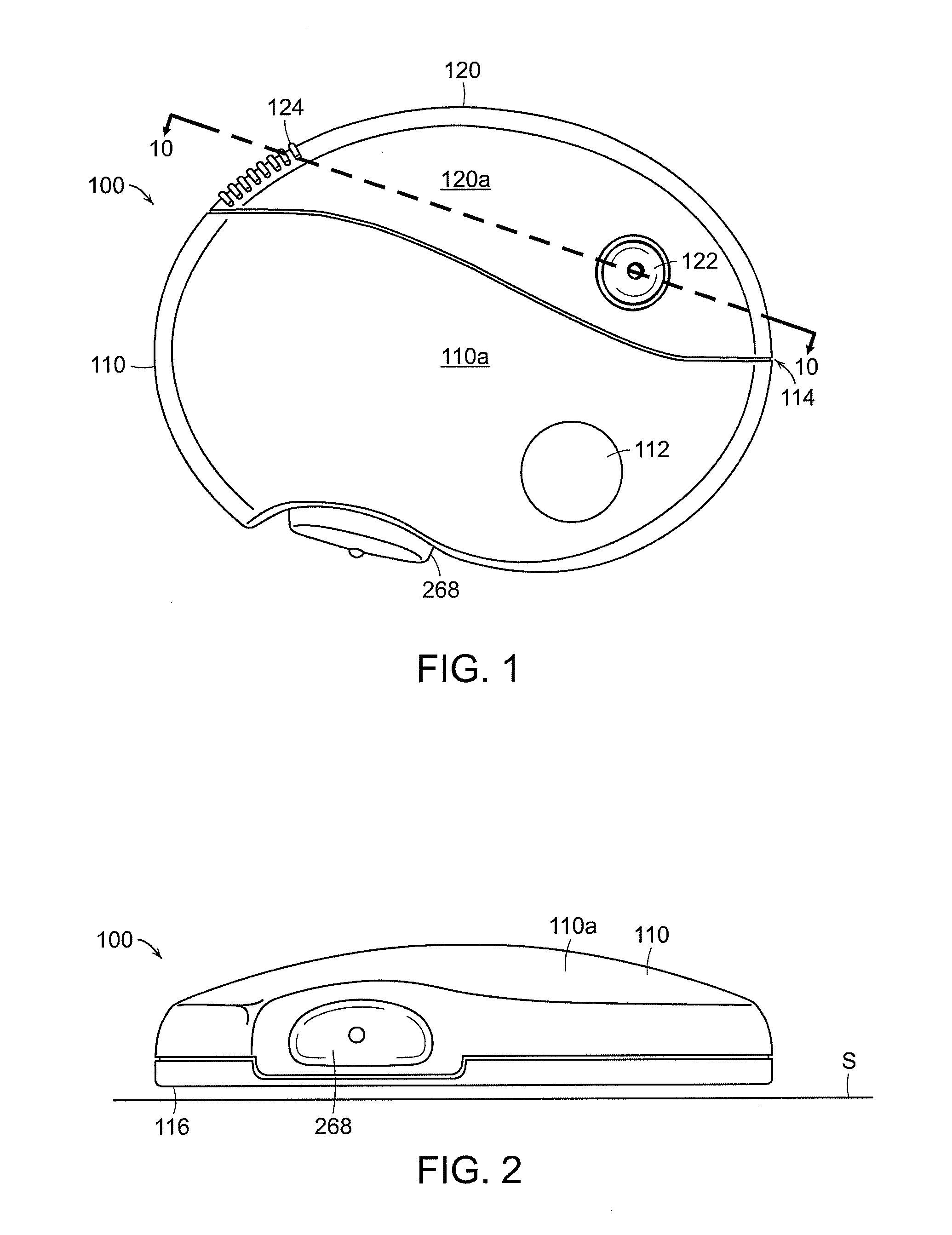
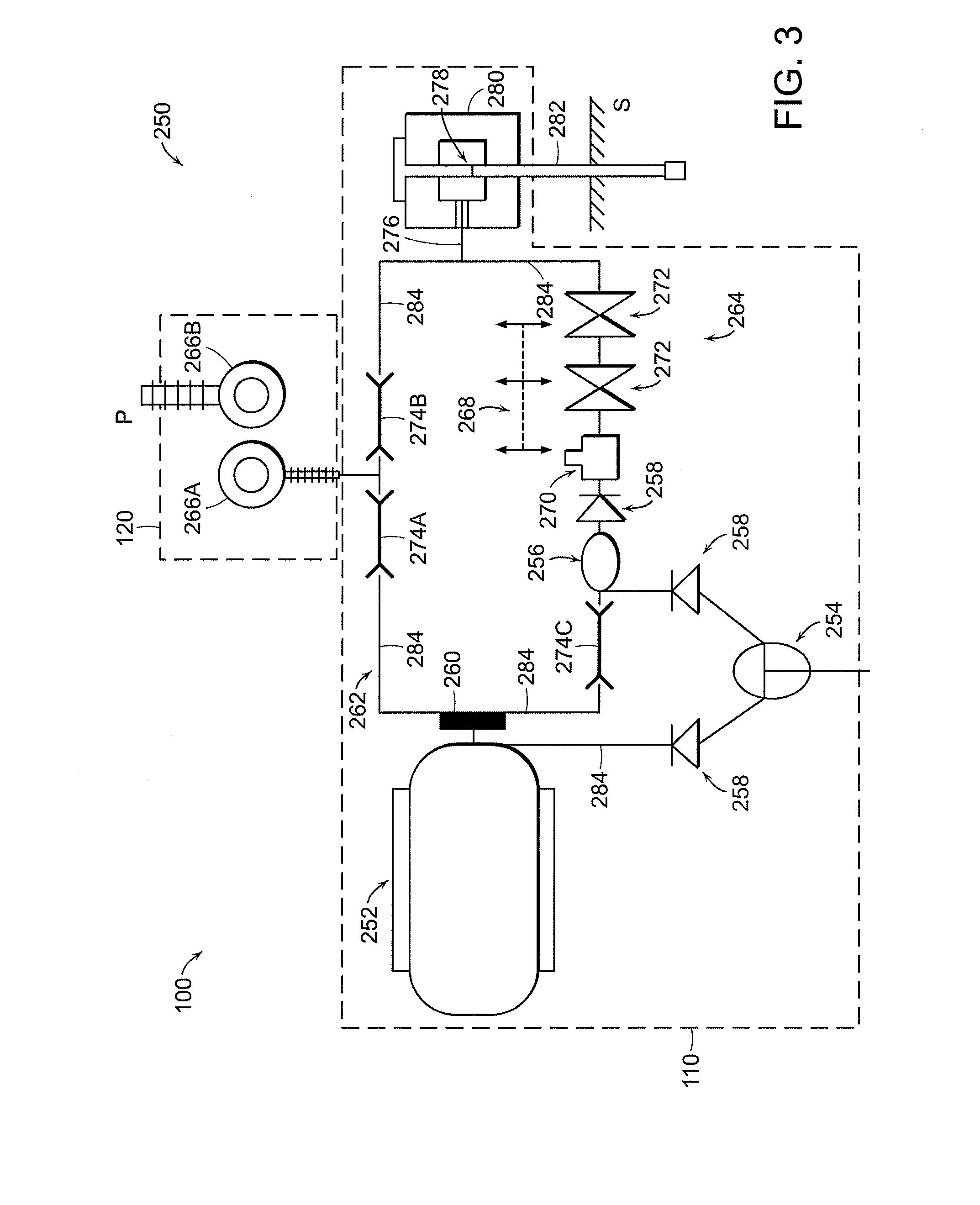
[0042]FIGS. 1 and 2 depict an embodiment of an assembled fluid medicament delivery device 100 having at least two modules, a patient attachment unit 110 and a separate indicator unit 120, each having a housing 110a, 120a, respectively. The depicted fluid medicament delivery device 100, when assembled, defines a substantially oval shape, although other shapes (circular, oblong, elliptical, etc.) are also contemplated. In general, an assembled device having round corners, smooth edges, etc., may be desirable, since the device is designed to be worn on the skin of a patient, underneath clothing. Other aspects of the device that make it generally unobtrusive during wear include a small size (only about several inches across) and a low profile. Other device shapes and sizes are also contemplated.

[0043]The patient attachment unit 110 includes a bolus button 268 for delivering a dose of fluid medicament, as described below. A cannula insertion device (See FIG. 13A) inserts a cannula throug...


PUM


Abstract

A fluid medicament delivery device includes a patient attachment unit, containing the fluid medicament, and an indicator unit adapted to be detachably coupled to the patient attachment unit. A method for monitoring the fluid medicament includes independently setting a flow rate of a fluid medicament with the patient attachment unit. A pressure and / or a flow rate of the fluid medicament is sensed with a sensor located in a separate indicator unit in a sensing mode. A status of the fluid medicament delivery device is determined based at least in part on the pressure and / or the flow rate.

Description

FIELD OF THE INVENTION[0001]This invention relates generally to medicament delivery devices and, more specifically, to medicament infusion devices that utilize a reusable indicator unit and a disposable medicament-delivery unit.BACKGROUND[0002]Medicament infusion devices are utilized to deliver liquid fluid medicine to patients. For example, insulin infusion devices are often used by persons with diabetes to maintain adequate insulin levels throughout the day or to increase insulin levels during mealtime. These insulin infusion devices can replace the syringe-based injections common among those with diabetes.[0003]Insulin infusion devices are available in several forms, and include several common components. Generally, an infusion device includes a housing that may be worn on a patient's clothing (a belt, for example) or on the patient himself, and that contains a number of mechanical and electrical components. A reservoir holds the insulin and an electro-mechanical pump mechanism (...

Claims


Application Information

Patent Timeline
Patent Type & Authority Applications(United States)
IPC IPC(8): G08B19/00A61M5/14
CPCA61M5/1413A61M5/5086A61M5/16854A61M5/16886A61M2005/14252A61M2005/14264A61M2005/14268A61M2005/16863A61M2205/0244A61M2205/18A61M2205/3331A61M2205/3334A61M2205/3344A61M2205/3358A61M2205/581A61M2205/582A61M2205/583A61M2205/70A61M5/14248A61M5/14A61M5/16831A61M2205/50A61M2205/587A61M2207/00
Inventor PEATFIELD, GREGGRAVESEN, PETER
Owner CEQUR SA
Learn More